EasyManua.ls Logo

Adler Power CO-SinusUPS-400W User Manual

Adler Power CO-SinusUPS-400W
4 pages
To Next Page IconTo Next Page
Page #1 background imageLoading...
Page #1 background image
14
SINE WAVE INVERTER
MODEL: CO-SinusUPS-400W
USER MANUAL
Please read and save this manual!
This manual is an important instruction that you should follow during
installation and maintenance of the inverter. Please read all instructions
before using the equipment and save this document for future reference.
CO-sinusUPS-400W-manual-R3, 20.03.10
7. SPECIFICATION
Model
CO-SinusUPS-400W
Output Power
500VA/400W
Input Voltage / Frequency
155 ÷ 290VAC ± 7VAC; 50Hz
Output Voltage Range (AC mode)
200 ÷ 250VAC ± 7VAC
Output Voltage and Frequency (Battery mode)
220VAC ± 10VAC / 50Hz
Transfer Time
max. 10ms
Battery Voltage
12VDC
Charging Current
max. 6A
Output Waveform (Battery mode)
Sine Wave
Operation Temperature
0 ÷ 40°C
Operation Humidity
30 ÷ 95%
Overload alarm
460W ± 50W
Dimensions
206 x 246 x 104mm
Net Weight
6kg
8. FRONT PANEL
9. BACK VIEW
1
2
1. Main control button.
2. LEDs of operation status.
1. Power cord.
2. Breaker
3. Battery Connector (12VDC)
4. Output Socket
5. Cooling Fan
APPLICATIONS: Heating and warm utility water systems,
solar systems, household appliances such as Home Theater,
TV, VCD, DVD, Lamp, Fan, etc.
Question and Answer IconNeed help?

Do you have a question about the Adler Power CO-SinusUPS-400W and is the answer not in the manual?

Adler Power CO-SinusUPS-400W Specifications

General IconGeneral
BrandAdler Power
ModelCO-SinusUPS-400W
CategoryInverter
LanguageEnglish

Summary

Front Panel Overview

Main Control Button

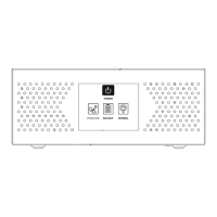
The primary button for controlling the inverter's functions and modes.

Operation Status LEDs

Indicator lights displaying the current operational status of the inverter.

Back Panel Connections

Power Cord Connection

The input terminal for connecting the AC power cord.

Circuit Breaker

Integrated breaker for protection against overloads and short circuits.

Battery Connector

Terminal for connecting the external 12VDC battery.

Output Socket

The socket where connected devices receive AC power.

Cooling Fan

Fan responsible for dissipating heat and maintaining optimal operating temperature.

Introduction to the Inverter

Main Features Summary

Operation Instructions

LED Indicators and Alarms

Troubleshooting Common Issues

Important Safety Guidelines