Do you have a question about the ADO A20F and is the answer not in the manual?
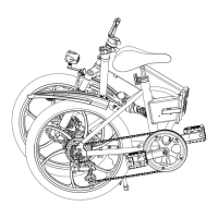
Step to unroll the main body of the ebike after unpacking.
Instructions for closing the body lock and fastening the safety lock.
Guide to using tools to secure the foot brace to the fender.
Steps for inserting and aligning the head tube, then securing handlebars.
Procedure for inserting the saddle and adjusting its height.
Instructions on aligning and tightening left and right pedals.
Steps for adjusting the headlight and inflating tires.
Guide on using the power key to start and shut down the ebike.
How to cycle through ODO, VOL, TRIP, and TIME on the display.
Instructions for increasing or decreasing the assist gear.
Steps for starting, stopping, and removing the ebike battery.
This document provides a quick installation guide and operation instructions for the ADO A16, A20, and A20F Ebike models. It covers the assembly of various components and basic usage of the electric bicycle.
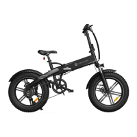
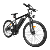
The ADO A16, A20, and A20F are electric bicycles designed for personal transportation. They feature a foldable body for easier storage and transport, an electric motor to assist pedaling, and a display to show various ride parameters. The ebike is equipped with essential components for safe and functional operation, including a headlight, pedals, a saddle, handlebars, and a kickstand. The electric assist system allows riders to choose different levels of power assistance, making rides less strenuous and suitable for various terrains and distances. The battery is removable, offering flexibility for charging and security.
The installation process begins by unpacking the bicycle and its accessories. The main body of the ebike needs to be unrolled and secured. This involves closing the body lock and fastening the safety lock to ensure the frame is rigid and safe for riding.
Next, the foot brace (kickstand) needs to be installed. This requires removing two 5mm hexagon screws from the foot brace, positioning the foot brace behind the fender, and then using the provided tool to re-lock the screws, securing it in place.
The head tube is then inserted into the front fork head tube. Proper alignment is crucial; the arrow on the label should align with the marking line, ensuring the bicycle head and body are vertical. Once aligned, the lock is opened, the tube is put down, and the 7mm hexagon screw driver is used to lock the screws. The head tube is then put up, the head lock is closed, and the safety lock is snapped into place.
The handlebar installation involves opening the handlebar lock, adjusting the height of the head to the rider's preference, and then locking it tightly. Similarly, the cross handle lock is opened to adjust the direction of the head grip, which is then locked tightly.
The saddle is inserted into the saddle tube, and its height is adjusted for comfortable riding before being locked tightly.
Pedal installation requires careful attention to the left and right pedals, marked with "L" and "R" respectively. The left pedal ("L" mark) is aligned with the crank thread and rotated counterclockwise to tighten. The right pedal ("R" mark) is aligned with the crank thread and rotated clockwise to tighten. An Hexagon screwdriver is used to ensure the pedals are securely fastened.
The headlight needs to be adjusted to a front 30-degree downward position using the 8mm multi-type wrench to twist the screws. Finally, the tires should be inflated using the provided air pump to the recommended pressure.
Before the first ride, the battery must be started. This involves inserting the key and twisting it 45 degrees counterclockwise. To disconnect the battery after use, the key is turned 45 degrees clockwise, and then removed. Removing the battery for charging or storage involves inserting the key, pressing it upward, and then rotating it 90 degrees clockwise. It's important to remove the key first, then take out the key, and then take out the battery to avoid damage.
The ebike's operation is controlled via a display panel. To start the ebike, the Power key is long-pressed for 3 seconds. To turn it off, the Power key is long-pressed for 3 seconds again while the ebike is on. When the ebike is on, pressing the Power key cycles through different display modes: ODO (total mileage), VOL (current battery voltage), TRIP (mileage traveled since the last start), and TIME (time since the start of the current ride).
The electric assist level can be adjusted using the "+" and "-" buttons. Pressing "+" increases the gear, resulting in faster speed, while pressing "-" lowers the gear, leading to slower speed. This allows riders to customize the level of assistance based on their needs and riding conditions.
While the manual primarily focuses on installation and initial operation, it implicitly suggests several maintenance aspects. The use of specific tools (5mm and 6mm Hexagon screw drivers, multi-type wrench) for assembly indicates that these tools will also be necessary for any future adjustments or minor repairs. The instruction to inflate tires implies regular tire pressure checks are part of routine maintenance. The removable battery system facilitates easy charging and replacement, contributing to the longevity of the ebike. Proper alignment of components during installation, such as the head tube and handlebars, is crucial for safe operation and also highlights the importance of checking these alignments periodically to ensure continued safety and performance. The guide's emphasis on securely locking all foldable parts (body lock, safety lock, head lock, handlebar lock, cross handle lock, saddle lock) suggests that these mechanisms should be regularly inspected for wear and proper function to maintain the structural integrity of the bicycle.
| Frame Material | Aluminum Alloy |
|---|---|
| Motor Power | 250W |
| Battery Capacity | 36V 10.4Ah |
| Brakes | Mechanical Disc Brakes |
| Type | Folding Electric Bike |
| Motor | Brushless Gear Motor |
| Gears | 7-Speed |
| Brake Type | Disc Brakes |
| Foldable | Yes |
| Tire Size | 20 inches |
| Battery | Removable Lithium-ion |
| Max Speed | 25 km/h (15.5 mph) |
| Range | 60-80 km |