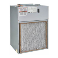
EasyManua.ls Logo

Adp S Series - User Manual

Adp S Series
14 pages
Print Icon
To Next Page IconTo Next Page
Loading...
AIR HANDLER SAFETY
S-series
Wall Mount Air Handlers
Installation Instructions
TABLE OF CONTENTS PAGE PAGE
2175 West Park Place Blvd., Stone Mountain, GA 30087
www.adpnow.com
Product improvement is a continuous process at Advanced Distributor Products. Therefore, product specifications are subject to change without notice
and without obligation on our part. Please contact your ADP representative or distributor to verify details.
© by Advanced Distributor Products. All rights reserved.
SAFETY CONSIDERATIONS
Your safety and the safety of others are very important.
We have provided many important safety messages in this manual and
on your appliance. Always read and obey all safety messages.
This is the safety alert symbol.
This symbol alerts you to potential hazards that can kill or hurt
you and others.
All safety messages will follow the safety alert symbol and signal word.
These signals words mean the following:
DANGER: You can be killed or seriously injured if you don’t
immediately follow instructions.
WARNING: Indicate a potentially hazardous situation which, if not
avoided, could result in death or serious injury.
CAUTION: Indicates a potentially hazardous situation which, if not
avoided, may result in minor or moderate injury. Caution may also
be used to alert against unsafe practices.
NOTICE: Indicates a statement of company policy as the message
relates directly or indirectly to the safety of personnel or protection of
property.
IMPORTANT: More detailed information concerning the statement of
company policy as the message relates directly or indirectly to the
safety of personnel or protection of property.
All safety messages will tell you what the potential hazard is, tell you how
to reduce the chance of injury, and tell you what can happen if the
instructions are not followed.
Air Handler Safety ................................................................ 1
General ............................................................................... 2
Receiving ............................................................................. 2
Installation Requirements .................................................... 2
Installation ............................................................................ 3
Ductwork .............................................................................. 3
Install Condensate Drain...................................................... 4
Metering Device ................................................................... 4
Refrigerant Line Installation ................................................. 5
Refrigerant Piping ................................................................ 5
Refrigerant Charging Instructions ........................................ 5
Filters ...................................................................................6
Electrical Requirements .......................................................6
Electrical Connections ........................................................6
Thermostat Connections ......................................................7
Electrical Data ......................................................................8
Blower Performance Data ....................................................8
Wiring Diagrams ................................................................10
Air Handler Checks ............................................................12
Air Handler Maintenance ...................................................12
Assistance or Service ........................................................12
Warranty ............................................................................13
IM-SAH-0654638-20
March 2024
Question and Answer IconNeed help?

Do you have a question about the Adp S Series and is the answer not in the manual?

Overview

This document provides installation instructions for S-series wall mount air handlers manufactured by Advanced Distributor Products (ADP). It covers safety considerations, general installation procedures, electrical requirements and connections, thermostat connections, blower performance data, wiring diagrams, air handler checks, maintenance, and warranty information.

Function Description:

The S-series wall mount air handlers are designed to be integrated into heating, ventilation, and air conditioning (HVAC) systems. They are suitable for free-air return when enclosed in a closet with a louvered door or flush-mounted in a wall. These units require a casing for proper installation. The air handler's primary function is to circulate air and facilitate heat exchange, working in conjunction with an outdoor condensing unit for cooling and potentially an electric heater for auxiliary heat.

Important Technical Specifications:

  • Electrical Requirements:
    • Factory configured for 240 Volt, single phase, 60 cycles.
    • 208 Volt applications require specific conversion procedures (refer to "208 Volt Conversion" in the "Make Electrical Connections" section).
    • Wire Gauge (AWG) based on Rating Plate Ampacity:
      • 21-30 Ampacity: 10 AWG
      • 31-40 Ampacity: 8 AWG
      • 41-60 Ampacity: 6 AWG
    • All field wiring must comply with National Electrical Code, UL requirements, and local codes.
    • The power supply must be sized and protected according to product specifications.
    • Copper conductors only are to be used for wiring.
    • For models with electric heat, the number of circuits needed to supply the heater with electrical power should be determined from the air handler Accessory Kit label.
  • Refrigerant Piping:
    • Refrigerant connections are 3/8" ODF Liquid and 3/4" ODF Suction.
    • Minimum 1.5" clearance from refrigerant brazing connections to cabinet or ceiling.
    • Brazing requires an alloy of silver or copper and phosphorus with a melting point above 1,100°F (soft solder is not permitted).
    • ADP recommends installing a filter drier and sight glass in the liquid line.
    • System evacuation to 500 microns is required for proper air and moisture removal (deep evacuation or triple evacuation method recommended).
  • Refrigerant Charging (Cooling Mode):
    • Outdoor temperature should be 60°F or higher.
    • Allow at least 15 minutes for pressures to stabilize between adjustments.
    • For micro-channel outdoor coils, make small (1 ounce or less) adjustments due to sensitivity.
    • TXV Charging: Recommended 12°F sub-cooling for AC units and 10°F sub-cooling for heat pump units. If equipped with an adjustable valve, adjust to 10°F superheat.
    • Fixed Orifice Charging (for A1 (R-410A & R-22) refrigerant): Superheat values vary with outdoor air temperature:
      • 60°F: 31°F
      • 65°F: 28°F
      • 70°F: 25°F
      • 75°F: 22°F
      • 80°F: 20°F
      • 85°F: 16°F
      • 90°F: 13°F
      • 95°F: 10°F
      • 100°F: 8°F
      • 105°F: 6°F
      • 110°F: 5°F
      • 115°F: 5°F
    • Temperatures are ±2°F unless otherwise recommended.
  • Airflow (Cooling Blower Speed):
    • Should be between 350 and 450 CFM per ton of cooling capacity (350 - 450 CFM per 12,000 BTU/HR) based on the outdoor unit's rating.
    • Minimum of 350 CFM airflow per ton (12,000 BTU/HR) of outdoor cooling capacity.
  • Ductwork: Must be fabricated and installed in accordance with local and/or national codes, including NFPA No. 90B standards for Air-Conditioning and Ventilating Systems.
  • Condensate Drain:
    • Primary and secondary drains are required.
    • Minimum 3/4" NPT PVC connector for condensate drain.
    • Pitch drain line at least 1" per 10' of horizontal run.
    • A trap is required in the primary drain line.
    • A secondary drain pan is recommended for installations in or above a living space.
  • Metering Device: Factory installed expansion valves (TXV) or florator pistons. TXV sensing bulb should be reattached and insulated at a 10 to 2 o'clock position on the suction line, no more than one foot from the connection.

Usage Features:

  • Installation Flexibility: Can be installed in a closet with a louvered door (requiring at least 1 square foot of face area per cooling ton) or flush-mounted in a wall.
  • Mounting Bracket: A wall hanging bracket is included for "on the wall" applications. It should be level, attached to studs (with 2" x 8" blocking recommended), and secured with 2" screws.
  • Flush Mount/In-Wall Applications: Requires recessing the air handler 2" to accommodate drain line connections. A notch in the stud may be needed for primary drain access. The unit should not protrude beyond the front of the stud to avoid interference with the louvered wall grille.
  • Thermostat Connections: Detailed wiring diagrams are provided for 3-speed PSC and 5-speed high efficiency ECM motors, for both cooling applications with electric heat and heat pump applications with electric heat. For 2-stage outdoor units, the thermostat calls for the desired CFM for 1st and 2nd stage operation.
  • Filters: Not provided with the unit; must be supplied and installed by the installer in the return air system. A field-installed filter grille is recommended for easy access. Filters must have adequate face area for the rated air quantity.
  • Thermal Expansion Valve (TXV) Maintenance: Instructions are provided for replacing the piston in the TXV assembly, including removing the existing piston, inserting the desired piston, inspecting the O-Ring, and reinstalling the hex nut to a torque of 10 ft-lbs.

Maintenance Features:

  • General Maintenance: The unit should be serviced by a qualified installer or servicing agency at the beginning of each heating season.
  • Blower Operation Check: Set the thermostat to FAN ON; the indoor blower should come on.
  • Electric Heater Check (if used):
    • Set the thermostat to call for auxiliary heat (approximately 5°F above ambient temperature). The indoor blower and auxiliary heat should come on together. Allow a minimum of three minutes for all sequencers to cycle on.
    • Set the thermostat not to call for heat. Allow up to five minutes for all sequencers to cycle off.
  • Airflow Check: Verify cooling blower speed provides 350-450 CFM per ton of cooling capacity. Adjust blower speed if the outdoor unit is smaller than the maximum cooling capacity rating of the air handler.
  • Safety: Emphasizes disconnecting all power supplies before servicing, replacing all parts and panels before operating to prevent electrical shock. It also warns against supplying the appliance through an external switching device (e.g., timer) to avoid inadvertent resetting of the thermal cut-out.
  • Warranty: Advanced Distributor Products (ADP) warrants products to be of merchantable quality, free of defects in material and workmanship, under normal use and service, for a period of five (5) years from the date of installation, not to exceed six (6) years from the date of manufacture. An extended warranty may be available upon registration. Registration requirements are prohibited in some states or provinces.

Adp S Series Specifications

General IconGeneral
BrandAdp
ModelS Series
CategoryAir Handlers
LanguageEnglish

Related product manuals