Page 11
UHRS-30/105
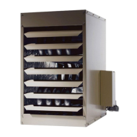
Unit may be installed as shown in gure 4 o r rotated
180°.
1 - Push each louver to the right to depress spring and
release locking tab on the other end (locking tab
keeps the louver in place for shipping).
2 - If installing unit in a rotated position - release locking
tabs in the same manner as previous step. Rotate
each louver 180° and reinstall. Remove and retain
screws securing access panel. Rotate access panel
180° and re-secure using retained screws.
3 - Rotate louvers to direct airow as desired.
4 - Choose location for mounting brackets.
5 - Align mounting brackets with pilot holes on the top or
bottom (when rotating) edge of the unit. Secure with
screws provided in bag assembly.
6 - To support unit, secure mounting bracket to ceiling
joist or truss. Unit may also be supported using
support rods as shown in gure 4.
7 - Install the 3D brand badge provided with the unit.
INSTALL UNIT HEATER
SUPPORT
RODS
MOUNTING
BRACKETS
(2)
ACCESS PANEL
(030 / 105 SHOWN)
FIGURE 4
Rotation of Combustion Air Inducer (UHCM-125 & 150 Only)
The combustion air inducer on UHCM-125 & 150 may
be rotated 90° either to the left or right of the original
vertical position in order to better suit the application.
NOTE - It is not permissible to rotate the combustion
air inducer on UHRS-030/105 and UHCM-175/400.
Rotate the combustion air inducer assembly as follows:
1 - Remove the heater from the carton. Decide the best
unit heater orientation. The vent can be installed in
one of three discharge positions: up, left, or right.
2 - If the inducer is to be rotated, follow the instructions
in this section; otherwise, refer to instructions under
“Venting” section.
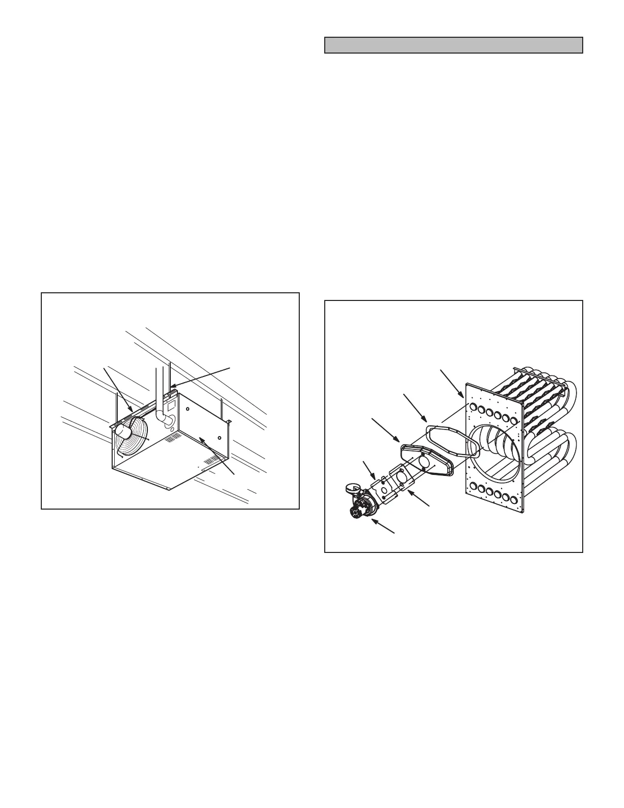
3 - Before making an electrical or gas connections, use
a socket to remove the four screws which secure the
combustion air inducer to the ue box. See gure 5.
4 - Rotate the inducer 90° to the desired position.
Reinsert and tighten the inducer securing screws.
5 - The unit heater is now ready for installation as
described in the Venting section.
FLUE BOX AND COMBUSTION AIR
INDUCER ASSEMBLY
125/150
FLUE BOX
FLUE BOX
GASKET
ORIFICE
PLATE
VEST PANEL
ORIFICE
PLATE GASKET
COMBUSTION
AIR INDUCER
FIGURE 5
 Loading...