Page 9
*6” is for single wall. Double wall B-vent clearance will be in accordance
with the manufacturer’s listing.
**Access panel or control box side of unit should have 24” (610mm)
clearance.
Additional Requirements
The Commonwealth of Massachusetts stipulates the fol-
lowing additional requirements:
1 - Gas furnaces shall be installed by a licensed
plumber or gas tter only.
2 - The gas cock must be “T handle” type.
Unit Heater Installation
The appliance shall not be installed downstream from
evaporator coils or cooling units.
Install the unit in the desired location as governed by
clearances, vent connection, air direction, gas supply,
electrical supply and service accessibility.
Unit is shipped ready for installation.
TABLE 2
MAXIMUM MOUNTING HEIGHTS
Unit Feet (Meters)
UHRS-030/075 10 (3.0)
UHRS-090/105 12 (3.7)
UHCM-125/150 16 (4.9)
UHCM-175/200 20 (6.1)
UHCM-250/400 30 (9.1)
TABLE 1
UNIT CLEARANCES TO COMBUSTIBLE MATERIALS
Unit
Top Side** Bottom Back Flue
in mm in mm in mm in mm in mm
030/105 1 25 1 25 1 25 18 457 6* 152
125/400 6 152 18 457 1 25 18 457 6 152
UHCM-125/400 UNITS
Four mounting nuts are furnished. Refer to dimension
illustration.
Mounting nuts will accommodate 3/8” x 16
threaded rods.
CAUTION
Do not install unit heaters in close proximity to re
sprinklers. Unit heater normal operating temperatures
could result in re sprinkler activation.
1 - Push each louver to the left to depress spring and
release locking tab on the other end (locking tab
keeps the louver in place for shipping).
2 - Rotate louvers to direct airow as desired.
3- Cut threaded rods to desired length and slide a 3/8”
nut onto the rod.
4 - Slide a at washer onto the threaded rod AFTER the
nut (7/16” inside diameter X 1” outside diameter X
1/16” thick washer).
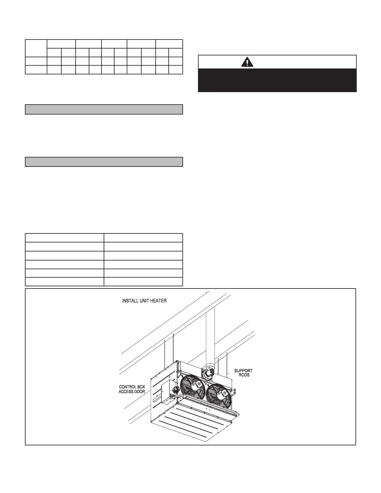
5 - Screw the rods (four) into the mounting nuts on the
unit. See gure 1.
6 - Tighten nuts to secure unit to rods.
7 - Install the 3D brand badge provided with the unit.
8 - Remove and discard the shipping brackets. Replace
four screws on each side. See gure 2.
9 - Install the burner box hood. See gure 3.
10- 175/400 Units Only - Install the ue transition, provided
with the unit, onto the combustion air blower ue outlet.
If needed, loosen the upper right two or three screws
securing the combustion air blower. Slide the transition into
place and secure loosened screws.
FIGURE 1
 Loading...