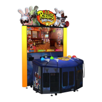
Do you have a question about the Adrenaline Amusements Rabbids Hollywood and is the answer not in the manual?
| Developer | Adrenaline Amusements |
|---|---|
| Cabinet Style | Upright |
| Sound | Stereo |
| Tickets | Yes |
| Players | 1 |
| Game Type | Redemption |
| Power Requirements | 110V |
| Type | Arcade |
Essential safety precautions for operating the arcade unit and preventing electrical hazards.
Recommended indoor operating temperature and humidity levels for the cabinet.
Specifies the required voltage and power consumption for the unit.
Instructions on gameplay mechanics, objectives, and player interaction within the game.
Details on the physical components and capabilities of the arcade unit.
Specifications regarding the physical dimensions and shipping size of the cabinet.
Step-by-step guide for the initial assembly of the arcade unit.
Procedure for detaching and reattaching the screen module assembly.
Instructions for attaching the header components to the main unit.
Steps to access the internal components and settings panel of the unit.
Guide to navigating and configuring game settings and operational parameters.
Diagram and description of all physical ports and connections on the computer.
Solutions for issues related to the accuracy and functionality of the gun tracking system.
Process for remapping controller IDs to ensure correct player identification.
General overview of common issues and diagnostic procedures for the unit.
Steps to resolve problems related to the display and picture output.
Steps to resolve issues concerning sound volume or lack thereof.
Procedures for diagnosing and fixing problems with the RGB LED lighting system.
Instructions on how to replace the printed circuit boards for the RGB LED strips.
Guide for connecting the unit to a Wi-Fi network for online features.
Fix for operator settings reverting to default after power cycles.
Troubleshooting steps for when the internal computer fails to power on.
List of individual components that make up the physical cabinet structure.
Identification and part numbers for internal electronic components and computer hardware.
Details on parts related to the header assembly and LED lighting components.
List of various cables used in the unit, including their specifications and part numbers.
Specific part numbers for the pre-assembled wiring harnesses used in the unit.
Listing of miscellaneous parts not covered in other categories.
Schematic diagram of the Input/Output (I/O) board with connector pinouts.
Detailed wiring diagrams illustrating connections to the I/O board for various functions.
Wiring diagrams specific to the ticket dispenser mechanisms and their connections.
Visual guide showing speaker connections and wire color coding to amplifiers.
Diagrams illustrating how power is distributed throughout the arcade unit.
Schematics detailing the connections and operation of the RGB LED lighting system.
Specific wiring diagram for Channel 1 of the RGB LED controller.
Specific wiring diagram for Channel 2 of the RGB LED controller.
Procedure for restoring the unit's software to its original state using a USB flash drive.
Configuration settings and connection requirements for the Embed card reader system.
Information regarding the warranty period, coverage, and claim procedures.