EasyManua.ls Logo

ADT TSSC-BASE User Manual

ADT TSSC-BASE
8 pages
To Next Page IconTo Next Page
Page #1 background imageLoading...
Page #1 background image
TSSC-BASE
Base Control Unit and
TSSC-KP Wireless Bidirectional Alpha Keypad
User Guide
BASE FEATURES
Display
The TSSC-BASE is a wireless Control Unit that allows you to perform system arming and disarming
functions, as well as to monitor the status of your security system.
TSSC-BASE w/Protective Door Removed
Base unit LEDs
LED Off Red Amber Green
Flashing
Green
Flashing
Amber
Flashing
Red
Alternating
Flashing
POWER
No AC
AC
BATTERY
(see note 1)
Low
Battery/
Missing
Battery
Charging Battery -
Normal
In
Programming
- Red
STATUS
Not Ready
to Arm
Armed System
Trouble
Ready to
Arm
Device
Trouble
Can Arm
Device
Trouble
Cannot
Arm
Alarm/Alarm
Memory
In
Programming
- Off
NETWORK
(see note 2)
Not
Configured
No
Ethernet
Link
Link but
Not
Connected
to Central
Station
Ethernet
Link
In
Programming
- Green
CELLULAR
Not
Configured
No
Connection
or Low
Signal
Good
Signal
Cell but No
Data
SIM Error In
Programming
- Off
NOTE 1: During Sleep Mode only the BATTERY LED is active.
NOTE 2: This LED may remain in the Amber state for up to 24 Hours until a report is sent
and acknowledged by the central station.
Question and Answer IconNeed help?

Do you have a question about the ADT TSSC-BASE and is the answer not in the manual?

ADT TSSC-BASE Specifications

General IconGeneral
BrandADT
ModelTSSC-BASE
CategoryControl Unit
LanguageEnglish

Summary

BASE FEATURES

Display

Describes the TSSC-BASE as a wireless Control Unit for system arming, disarming, and status monitoring.

Base Unit LEDs

Details the states and meanings of LEDs on the Base unit for POWER, STATUS, NETWORK, and CELLULAR.

KEYPAD FEATURES

Keypad Display

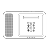
Describes the TSSC-KP as a wireless keypad for system functions and status display.

Keypad Sounder

Explains the sounder's function for fire, burglary, and panic alarms.

Keypad LEDs

Details the states and meanings of LEDs on the Keypad for POWER, TROUBLE, and STATUS.

Special Function Keys

Highlights special function keys on the keypad.

KEYPAD KEY DESCRIPTIONS

General Key Functions

Provides descriptions for keys like OFF, AWAY, STAY, MAX, TEST, BYPASS, INSTANT, CODE, CHIME, READY, [#].

Special Function Keys (Keypad Only)

Explains that A, B, C keys can be programmed as Panic Alarm Activation keys.

GENERAL OPERATION

System Status and Arming

Explains how to check and update the system status display and arm the system.

Disarming and Zone Bypassing

Details how to disarm the system and bypass individual or multiple zones.

User Codes and Authority Levels

Covers adding, changing, and deleting user codes and their authority levels.

SYSTEM MODES AND TESTING

Chime Mode

Explains how to use and activate the chime mode for door/window openings when disarmed.

Keypad Tones

Describes keypad beeps for periodic reminders and trouble conditions.

Quick Exit

Instructions for initiating the Quick Exit feature in Stay, Instant, and Night-Stay modes.

Host Check-in

Explains the message displayed at the Keypad during host check-in intervals.

Test Mode

Guides through testing system protection points and exiting test mode.

BATTERY REPLACEMENT PROCEDURES

Wall Mounted Keypad Battery Replacement

Step-by-step instructions for replacing the battery in a wall-mounted keypad.

Desk Mounted Keypad Battery Replacement

Step-by-step instructions for replacing the battery in a desk-mounted keypad.

SYSTEM LIMITATIONS AND COMPLIANCE

Alarm System Limitations

Discusses system limitations, potential failure points, and user responsibilities.

FCC, IC, and RF Exposure Information

Contains FCC/IC compliance statements, usage restrictions, and RF exposure safety guidelines.

WARRANTY AND INSTALLATION TERMS

Limited Warranty

Details the terms and conditions of the equipment warranty, including coverage and exclusions.

Installation Terms

Outlines ADT's installation responsibilities and customer requirements.