C-1
p r i t y
Modbus paraity:
n.stb.1/n.stb.2/odd/even
N s t B 2
D-3
9 6 0 0
b a u d
Modbus baud rate:
1200/2400/4800/9600/19
200/38400
D-2
1
a d r e s
Address:
1~255
D-1
g r o u p
r s 4 8 5
RS485
GROUP
1S back
ENT
P
Current:
A0-10 mA A0-20: mA A 4-20 mA:0~10 0~20 . :4~20
A 4B20 mA Ab10 ± mA. :4~12~20 : 10
Ab20 ± mA: 20
Voltage:
V0-5:0~5V V1-5:1~5V V0-10:0~10V
V0B5:0~2.5~5V V1B5:1~3~5V
V0B10 V Vb5:± V Vb10:± V:0~5~10 5 10
C-2
Output signal of type and
range :
A A /A.0-10/ .0-20 .4-20/
A B /A B. A B /.4 .20 . 10/ . .20
V V. /V V B /.0-5/ 1-5 .0-10/ .0 .5
C-3
Analogue output low-scale:
-19999~29999
C-4
Analogue output hi-scale:
-19999~29999
C-5
Analogue output low fine
tunning::
C-6
Analogue output Hi fine tunning:
-32768~32767
C-7
Reset fine tunning:
NONE/AO ZRO AO SPN BOTH. / . /
n on e (NONE): Does not clear the correction
a Oz r o (Ao.Zro): Clear the lower limit of fine-tuning
a Os p n (Ao.SPn): Clear upper limit of fine-tuning
b ot h (both): Clear the lower limit, upper limit of fine-tuning
correction
C-8
Output limit:0~110 %
9 24/
Parameter Description
ExplainIndex
AO corresponding the parameters:
v a v g. :3 Phase average voltage
i a v g. :3 Phase apparent power
f r e q :Frequency
p . t l :3 Phase active power
q . t l :3 Phase reactive power
s . t l :3 Phase apparent power
p f . a v g :3 Phase average power factor
v a :Phase A voltage
v b :Phase B voltage
v c :Phase voltageC
i a :Phase A current
i b :Phase currentB
i c :Phase currentC
AO corresponding the parameters:
p f - a :Phase A power factor
p f - b :Phase B power factor
p f - c :Phase C power factor
p - a :Phase A active power
p - b :Phase B active power
p - c :Phase C active power
q - a :Phase A reactive power
q - b :Phase B reactive power
q - c :Phase C reactive power
s - a :Phase A apparent power
s - b :Phase B apparent power
s - c :Phase C apparent power
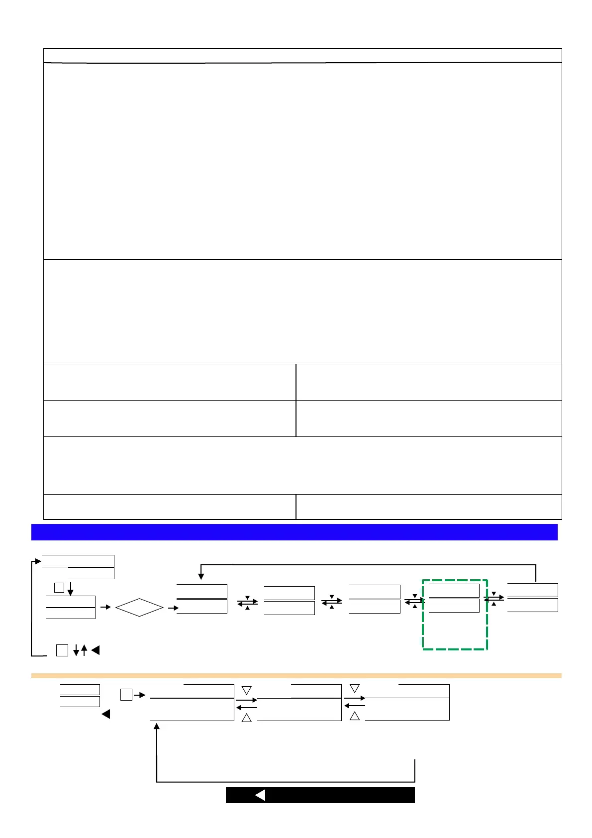
g r o u p
p u l s e
g r o u p
r s 4 8 5
g r o u p
a o
RELAY
GROUP
g r o u p
r e l a y
e n t er
P c o de
NO
YES
ENT
P
ENT
P
1S back
2 2 ) 0
1 0 ) 0
) 0
ANALOGUE
OUTPUT
GROUP
RS485
GROUP
PULSE
GROUP
INPUT
GROUP
g r o u p
i n p u t
Password
P.code
Correct
Default:1000
PV value
V A
W
Engineer level
Press sec escape to measuring page1
En d te rm in al o hm
ADEFGHI -1,:JKL)*MNO.PQNOMRS.<)
*3 4RSTUVWP4W.3
)*1 2 4,1-10~1-27XYZRSP W
)*1 4,1-14/1-1 ~ XYZRSP3W 6 27
)*3 4,1-1 1-1 /1-1 1- /P3W.1 3~ 5 7/1-18/ 20 1-21/1-23/1-24/1-
26/1-27XYZRS
)*3 4,1-1 1- /1- XYZRSP3W.2 7/ 20 23/1-26
)*3 4,1-1 1- /1- XYZRSP3W.3 7/ 20 23/1-26
)*3 4,1-1 1- /1-P4W.1 4~15/ 17~18 20~21/1-23~24/1-26~27
XYZRS
)*+,:1 p 2 w 1 p 3 w 3 p 3 w .1 3 p 3w .2 3p 3w .3/ / / / /
3 p 4 w .1 3 p 4 w .3/
"#$%&':
v a v g. ()*+,-.:
i a v g. ()*/,-.:
f r e q :
2345.
p . t l :()673.
q . t l :()6873.
s . t l :()69:73.
p f . a vg :(),-73;
%45.
v a : )*+.45A
vb :B)*+.45
vc :C)*+.45
ia :A)*/.45
ib :B)*/.45
ic :C)*/.45
p f - a :A)7345.
pf-b :B)7345.
pf-c :C)7345.
p - a :A)7345.
p-b :B)7345.
p-c :C)7345.
q - a :A)87345.
q-b :B)87345.
q-c :C)87345.
s - a :A)9:7345
s - b :B)9:7345
s - c :C)9:7345
RELAY / PULSE output of the outputs can
only choose a functional output
EX: Select PULSE output and then RELAY
function no output and vice versa
Clamp CT
Optional of Clamp CT, make sure
(1)CT of the SN number with the
CPM-10 SN number, as shown
( )2 On the label
A A Phase B B: - ; : -
Phase C C Phase; : - ;
According to the phase matching
Relay Pulse output
CL
BK
AK
AL
BL
CK
, ,0123CT4 56789:; <=>?@A
 Loading...