J2
J3
TOP PANEL
11
12
13 16
15
14
30V/60mA
CSM-
V mA
7 8 9 10
L
N
G
L
N
G
1A
ADH:AC85~264V
DC100~300V
ADL:AC/DC 20~65V
A1~A16: 20A/600Vac, M3.5, 22~12AWG;
13Kg-cm
:10A 300Vac, M2.6, 22~16AWG,
: 5Kg-cm
7.0mm max
7.0mm max
2.0mm max
Voltage
/
Current
16
16
B
A
16
B
A
J2
J3
J2
J3
4 24/
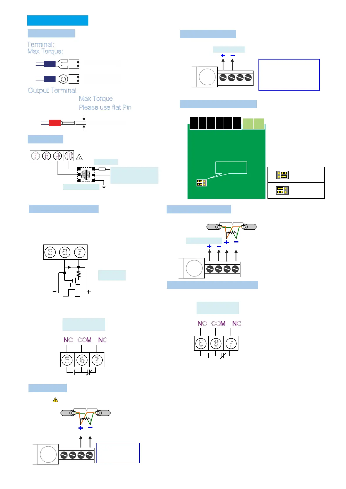
Analogue output
Wire terminal
Analogue output
Terminal:
Max Torque:
Output Terminal
Max Torque
Please use flat Pin
AUX
Fuse
Transformer filter
Pulse output
Due to limitation on number of terminal , pulse and relay
output is having same terminal, choose either one
Open collector:(OPC1)
Max load
RS Com485 .
Please earth isolation net to maintain signal quality
Wire distance: 1200M
:
120~300 ohm/0.25W
(typical: 150ohm)
End terminal ohm
Output mode: Selectable
within parameters setting,
voltage or current output need
to short J2 & J3 on output PCB
module.
Analogue output
points
Output short
:Current
:Voltage
Analogue + RS485
Voltage
/
Current
5A/230V 5A/115V,
COM NC
5 6 7
NO
Relay Pulse output OPR1:( )
Contact:
5A/230V 5A/115V,
COM NC
5 6 7
NO
Contact:
Alarm Relay output:(OR1)
Action frequency
less than 30HZ
5 6 7
E- C +
En d te rm in al o hm
ADEFGHI -1,:JKL)*MNO.PQNOMRS.<)
*3 4RSTUVWP4W.3
)*1 2 4,1-10~1-27XYZRSP W
)*1 4,1-14/1-1 ~ XYZRSP3W 6 27
)*3 4,1-1 1-1 /1-1 1- /P3W.1 3~ 5 7/1-18/ 20 1-21/1-23/1-24/1-
26/1-27XYZRS
)*3 4,1-1 1- /1- XYZRSP3W.2 7/ 20 23/1-26
)*3 4,1-1 1- /1- XYZRSP3W.3 7/ 20 23/1-26
)*3 4,1-1 1- /1-P4W.1 4~15/ 17~18 20~21/1-23~24/1-26~27
XYZRS
)*+,:1 p 2 w 1 p 3 w 3 p 3 w .1 3 p 3w .2 3p 3w .3/ / / / /
3 p 4 w .1 3 p 4 w .3/
"#$%&':
v a v g. ()*+,-.:
i a v g. ()*/,-.:
f r e q :
2345.
p . t l :()673.
q . t l :()6873.
s . t l :()69:73.
p f . a vg :(),-73;
%45.
v a : )*+.45A
vb :B)*+.45
vc :C)*+.45
ia :A)*/.45
ib :B)*/.45
ic :C)*/.45
p f - a :A)7345.
pf-b :B)7345.
pf-c :C)7345.
p - a :A)7345.
p-b :B)7345.
p-c :C)7345.
q - a :A)87345.
q-b :B)87345.
q-c :C)87345.
s - a :A)9:7345
s - b :B)9:7345
s - c :C)9:7345
RELAY / PULSE output of the outputs can
only choose a functional output
EX: Select PULSE output and then RELAY
function no output and vice versa
Clamp CT
Optional of Clamp CT, make sure
(1)CT of the SN number with the
CPM-10 SN number, as shown
( )2 On the label
A A Phase B B: - ; : -
Phase C C Phase; : - ;
According to the phase matching
Relay Pulse output
CL
BK
AK
AL
BL
CK
, ,0123CT4 56789:; <=>?@A
 Loading...