Parameter setting(A-1),connection different.will have
a different display(tick shown)
Hold escape to measuring page
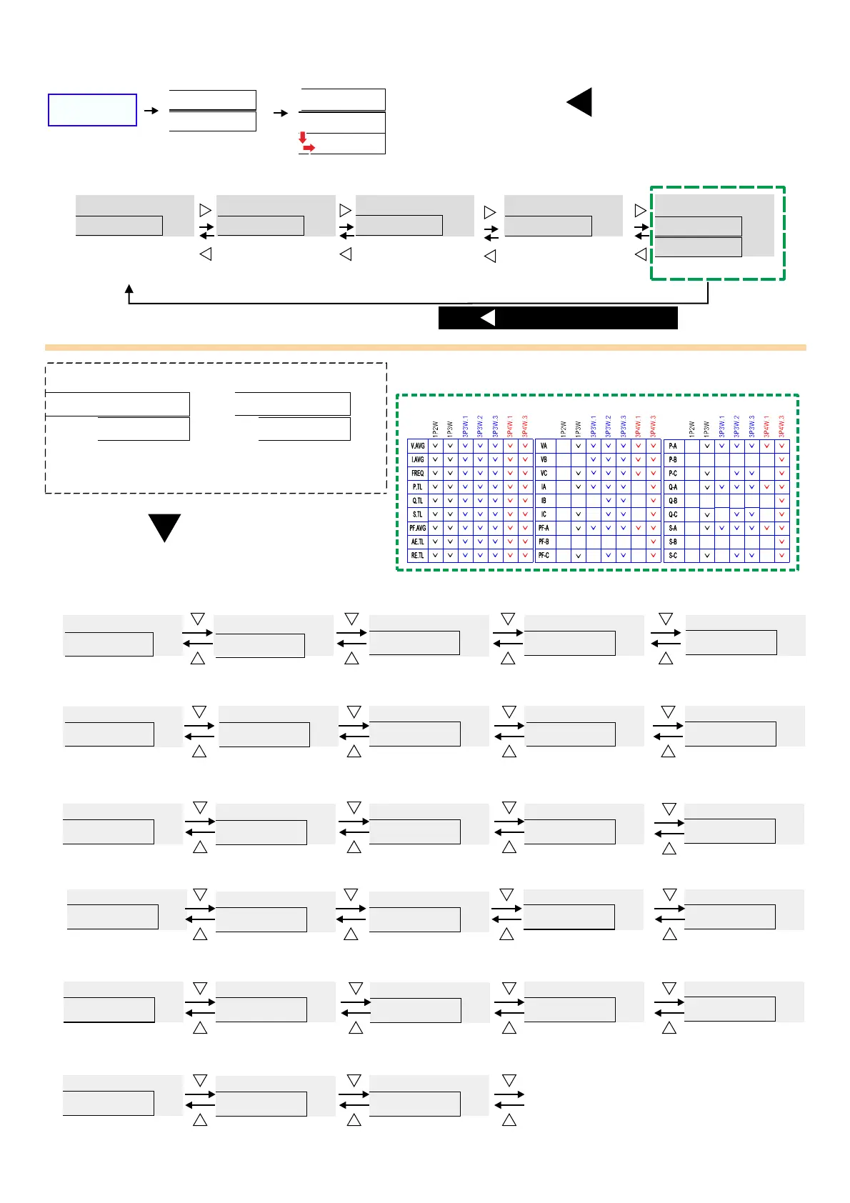
■Operation flow chart:
U V W # X Y
Measuring page
Press
Hold 1S
r 1 @ s p
Relay 1.2 setting point
0-2
r 1 # s p
Relay 1.3 setting point
0-3
rYrst
Reset relay
0-4
Relay 1.1 setting point
r 1 ! s p
0-1
v e r ! 3
c p m - 1 0
Version Model
0-5
Check wiring
before power up
* * * * * *
* * * * * *
3 p 3 w
c p m - 1 0
v e r 1 . 0
If no relay functions
Will only display
version and model
2 2 ) 0
1 0 ) 0
) 0
) 0
) 0
At 1-28 display function , choose V-A ( voltage/current)
,display as left, during KWH selection.
W
Self test
(LED all on)
Wire type
Model
Software
To relay setting
V
A
W Hr
/
W
d i S s l
1-28
q - c
1-24
s - a
1-25
s - b
1-26
s - c
1-27
u - b
1-11
U a v g
1-1
I a v g
1-2
f r e q
1-3
P t l
1-4
Q t l
1-5
S t l
1-6
p F a v g
1-7
a E t l
1-8
r E t l
1-9
u - a
1-10
u - c
1-12
I - a
1-13
I - b
1-14
I - c
1-15
p f - a
1-16
p f - b
1-17
p f - c
1-18
p - a
1-19
p - b
1-20
p - c
1-21
q - a
1-22
q - b
1-23
Back
to1-1
5 24/
3 Phase average
voltage
3 Phase
average current
Frequency
3 Phase active
power
3 Phase reactive
power
3 Phase
apparent power
3 Phase average
power factor
3 Phase total active
energy
3 Phase total
reactive energy
Phase A voltage
Phase B voltage
Phase C voltage
Phase A current
Phase B current
Phase C current
Phase A power factor
Phase B power factor
Phase C power factor
Phase A active
power
Phase B
active power
Phase C active
power
Phase A reactive
power
Phase B
reactive power
Phase C
reactive power
Phase A apparent
power
Phase B apparent
power
Phase C apparent power
Unit
V-A/KWH
En d te rm in al o hm
ADEFGHI -1,:JKL)*MNO.PQNOMRS.<)
*3 4RSTUVWP4W.3
)*1 2 4,1-10~1-27XYZRSP W
)*1 4,1-14/1-1 ~ XYZRSP3W 6 27
)*3 4,1-1 1-1 /1-1 1- /P3W.1 3~ 5 7/1-18/ 20 1-21/1-23/1-24/1-
26/1-27XYZRS
)*3 4,1-1 1- /1- XYZRSP3W.2 7/ 20 23/1-26
)*3 4,1-1 1- /1- XYZRSP3W.3 7/ 20 23/1-26
)*3 4,1-1 1- /1-P4W.1 4~15/ 17~18 20~21/1-23~24/1-26~27
XYZRS
)*+,:1 p 2 w 1 p 3 w 3 p 3 w .1 3 p 3w .2 3p 3w .3/ / / / /
3 p 4 w .1 3 p 4 w .3/
"#$%&':
v a v g. ()*+,-.:
i a v g. ()*/,-.:
f r e q :
2345.
p . t l :()673.
q . t l :()6873.
s . t l :()69:73.
p f . a vg :(),-73;
%45.
v a : )*+.45A
vb :B)*+.45
vc :C)*+.45
ia :A)*/.45
ib :B)*/.45
ic :C)*/.45
p f - a :A)7345.
pf-b :B)7345.
pf-c :C)7345.
p - a :A)7345.
p-b :B)7345.
p-c :C)7345.
q - a :A)87345.
q-b :B)87345.
q-c :C)87345.
s - a :A)9:7345
s - b :B)9:7345
s - c :C)9:7345
RELAY / PULSE output of the outputs can
only choose a functional output
EX: Select PULSE output and then RELAY
function no output and vice versa
Clamp CT
Optional of Clamp CT, make sure
(1)CT of the SN number with the
CPM-10 SN number, as shown
( )2 On the label
A A Phase B B: - ; : -
Phase C C Phase; : - ;
According to the phase matching
Relay Pulse output
CL
BK
AK
AL
BL
CK
, ,0123CT4 56789:; <=>?@A
 Loading...