2 61287703G1-22B
To install the OptiTap Connector option, refer to the Total Access 374 4-POTS,
4-GigE MDU ONT Installation and Maintenance Guide
(P/N 61287703G1-5) for instructions on this procedure.
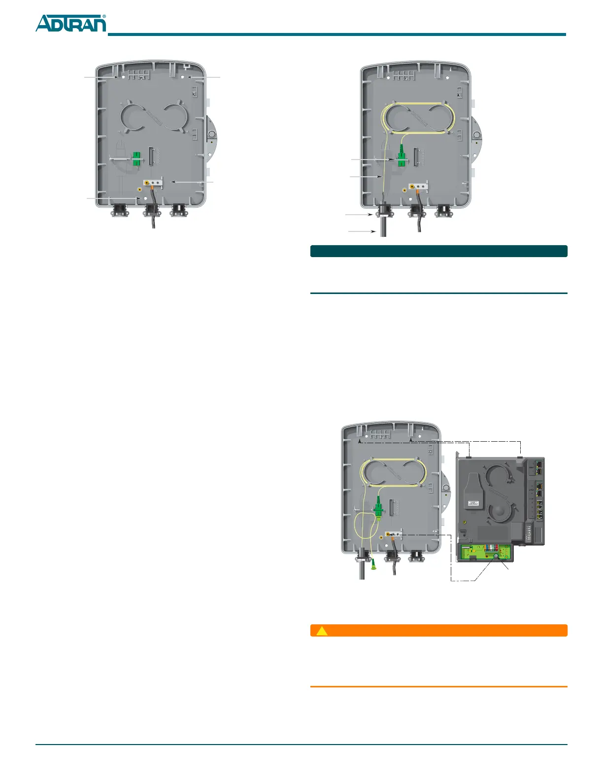
Install the Electronics Module
To install the Electronics Module in the NID Housing, complete the following
steps.
1. Connect the Fiber Jumper from the Bulkhead connector and route it
through the Fiber Guide as shown in the illustration on the following
page.
2. Align the tabs on the electronics Module with the snaps on the NID
Housing and snap the two together. See figure below.
3. Align the captive screw on the bottom of the Electronics Module with
the screw hole on the Ground Bar and tighten.
Refer to the figure on the next page to see how the Fiber Jumper is routed.
Connect Power/Alarm
Before making any power connections to this equipment, verify
the power is off (fuse removed/breaker tripped). This equipment
should only be operated from the type of certified/listed power
supply supplied by the manufacturer with the equipment.
The ONT is supplied with a 7-conductor Power/Alarm connector. The ONT is
also supplied with a 7-conductor socket equipped with a mating Insulation
Displacement Connector (IDC) plug. The 7-pin connector is typically green.
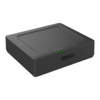
Fiber
Jumper
Bulkhead
Connector
Incoming
Fiber
Tie Wrap
Point
Note:
Connect the Fiber Jumper
to the Bulkhead connector.
Captive Screw
5. Route the ground wire 12 inches below finished grade by the shortest
and most direct route to the AC power ground system Multi Grounded
Neutral (MGN) of the customer premises. Ensure the wire is free of any
sharp bends.
6. Attach the ground wire to the side of the subscriber’s premises with
stainless steel half moon clamps or tie-wrap the ground wire to the riser
conduit of the Buried Fiber Drop.
7. Clean the MGN connector with emery cloth to insure a stable
connection.
8. Attach the ground wire from the ONT to the MGN connector with the
appropriate UL approved ground clamp/fitting.
9. Coat the connection with a metal corrosion preventative.
10. Attach a Warning Ground Tag to this grounding connection.
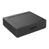
Install Straight Fiber
To install the Fiber Connection to the ONT, refer to the figure at the top of the
next column, and complete the following steps.
1. Route the Incoming Fiber through the rubber grommet as shown.
2. Trim the insulation on the fiber cable back so there is a sufficient length
of fiber to attach the fiber connector to the end of the fiber cable. Make
sure the Fiber Location Wire is trimmed so it does not enter the NID
housing, and that is it trimmed to below finished grade level.
3. Clean all fiber optical surfaces before and after splicing.
4. Splice the Incoming Fiber to a Fiber Jumper (shown in Yellow opposite)
using a Fiber Optical Fusion Splice Tool. DO NOT use a mechanical
splice as the APC connector may create a reflection at the splice point.
5. If no further installation steps are taken, route the Fiber Jumper that
attaches to the Electronics Module to the Bulkhead connector. This will
help keep the optics clean. Otherwise, proceed to the next step.
6. Tie wrap the Incoming Fiber Cable to the plastic housing that holds the
rubber grommets at the cable entry point.
Ground
Bar
Mounting
Hole
Mounting
Hole
Mounting
Hole
 Loading...