61287703G1-22B 3
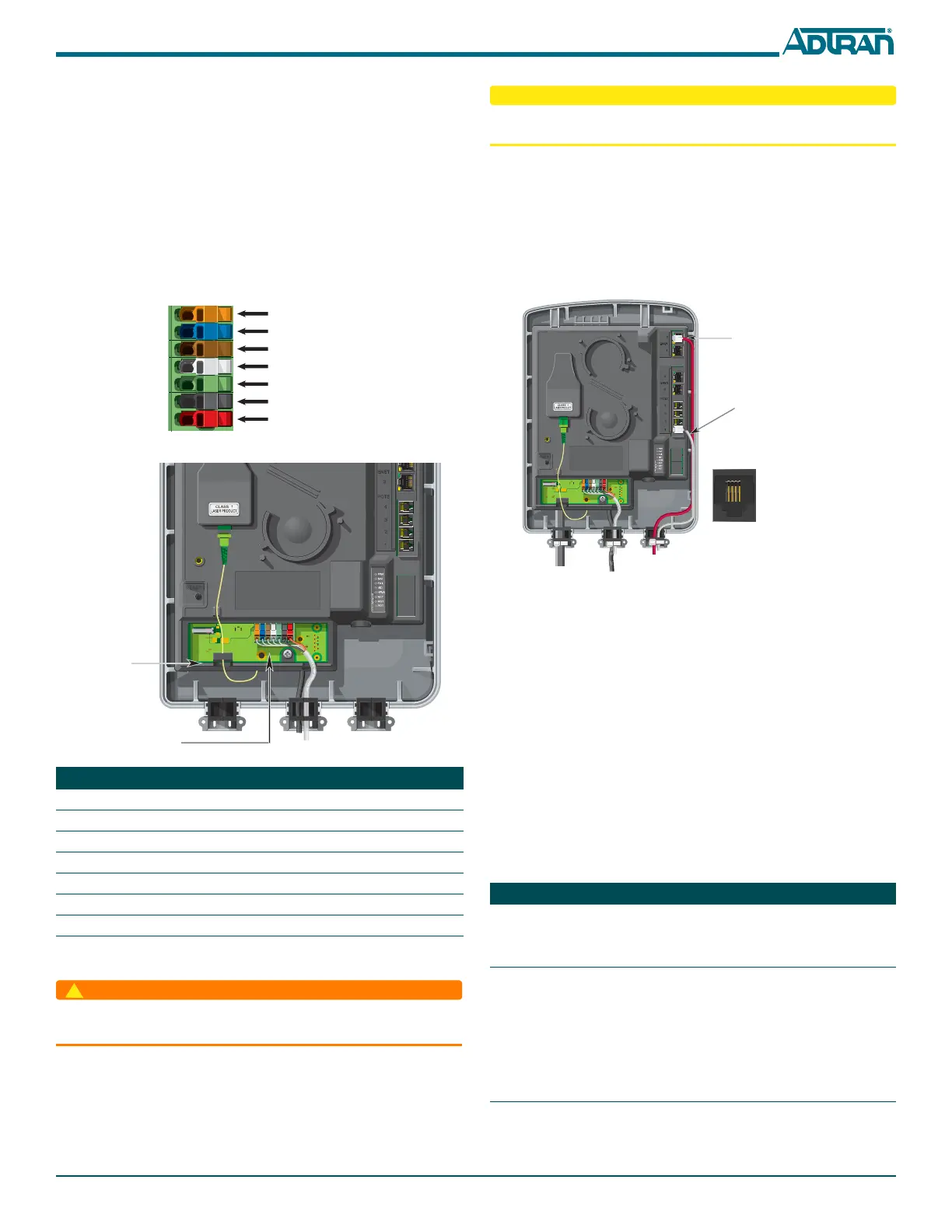
there are 7-conductors. Two are used for the 12 V supply and return. Five are
used for alarms, four from the UPS and one return wire. Refer to the following
steps and the two figures below to connect Power/Alarms to the ONT.
1. Remove the IDC connector from the Electronics Module.
2. Route the Power/Alarm wire through the rubber grommet as shown.
3. Terminate the 2 power leads (Pins 6 and 7), and the five UPS leads if
needed by raising the levers on the appropriate connector plugs.
4. Lower the levers using a flat-blade screwdriver. Internally the insulation
displacement connectors cut the insulation and make the electricaL
connection.
5. Reconnect the IDC Connector to the bottom of the Electronics Module.
6. Tie wrap the power cable to the plastic housing that holds the rubber
grommets at the cable entry point.
Install a Local Power Source
The ONT needs to be powered by a UL Listed Power Supply
suitable for the application with Output at LPS Levels.
Installation of the Local Power Source (LPS) will be dictated by on-site condi-
tions and local telephone company practices. Refer to theTotal Access 374 4-
POTS, 4-GigE MDU ONT
Installation and Maintenance Guide
(P/N 61287703G1-5) for complete information on connecting to the LPS.
PIN Description Color
1 Low Battery Orange
2 Battery Missing Blue
3 Replace Battery Brown
4 On Battery Grey
5 Signal Return Green
6 12 V Return Black
7+12 VDC Red
ORANGE (OG)
BLUE (BU)
BROWN (BN)
GREY (GY)
GREEN (GN)
BLACK (BK)
RED (RD)
Fiber Jumper
Routing
IDC
Connector
To reduce the risk of fire, use minimum no. 26 AWG telecommunications line
cord.
Install the UPS
Installation of the Uninterruptible Power Source (UPS) will be dictated by on-
site conditions and local telephone company practices. Refer to the installation
material that is provided with the UPS.
Connect Subscriber Services
For both POTS and Ethernet connections, refer to the following figure:
To terminate the POTS lines, complete the following steps.
1. Route the subscriber POTS wires through the rubber grommet.
2. Trim each wire to length.
3. Connect the wires to an RJ-11 connector plug. Refer to the POTS Pin-
Outs insert in the figure.
4. Insert the terminated RJ-11 connector in the appropriate POTS Port.
Connect Ethernet to the ONT
1. Route the Subscriber Ethernet wires through the same cable entry as the
POTS cables.
2. Insert into the appropriate ENET 1–4 socket.
3. Tie wrap both the POTS and Ethernet cables to the plastic housing that
holds the rubber grommets at the cable entry point.
LED STATUS
The LED table below provides the LED status for the ONT.
Label Status Indication
PWR
Off
Green
AC or battery off, UPS disconnected or
malfunctioning, PWR LED bad, defec-
tive LPS wiring
No failure
BAT
2
2
Off
Green
Green Flashing
Slow
Green Flashing
Fast
ONT boot or battery missing/not
equipped, defective battery, BAT LED
bad, defective LPS wiring
Battery equipped & no battery alarms
present
Loss of AC, or battery
Battery low
1 2 3 4
1 = Not Connected
2 = Tip
3 = Ring
4 = Not connected
POTS Pin-Outs
Ethernet
Termination
POTS
Termination
Note:
Wire color is for
clarity purposes
only.
 Loading...