4
STEP 2: INSTALLING THE AILERON AND FLAP CONTROL LINKAGE ASSEMBLIES
❑ Install one aileron servo into each wing panel. Each servo output
shaft should be toward the leading edge. You will need to install a 12"
long servo extension lead to each servo and run it through the wing.
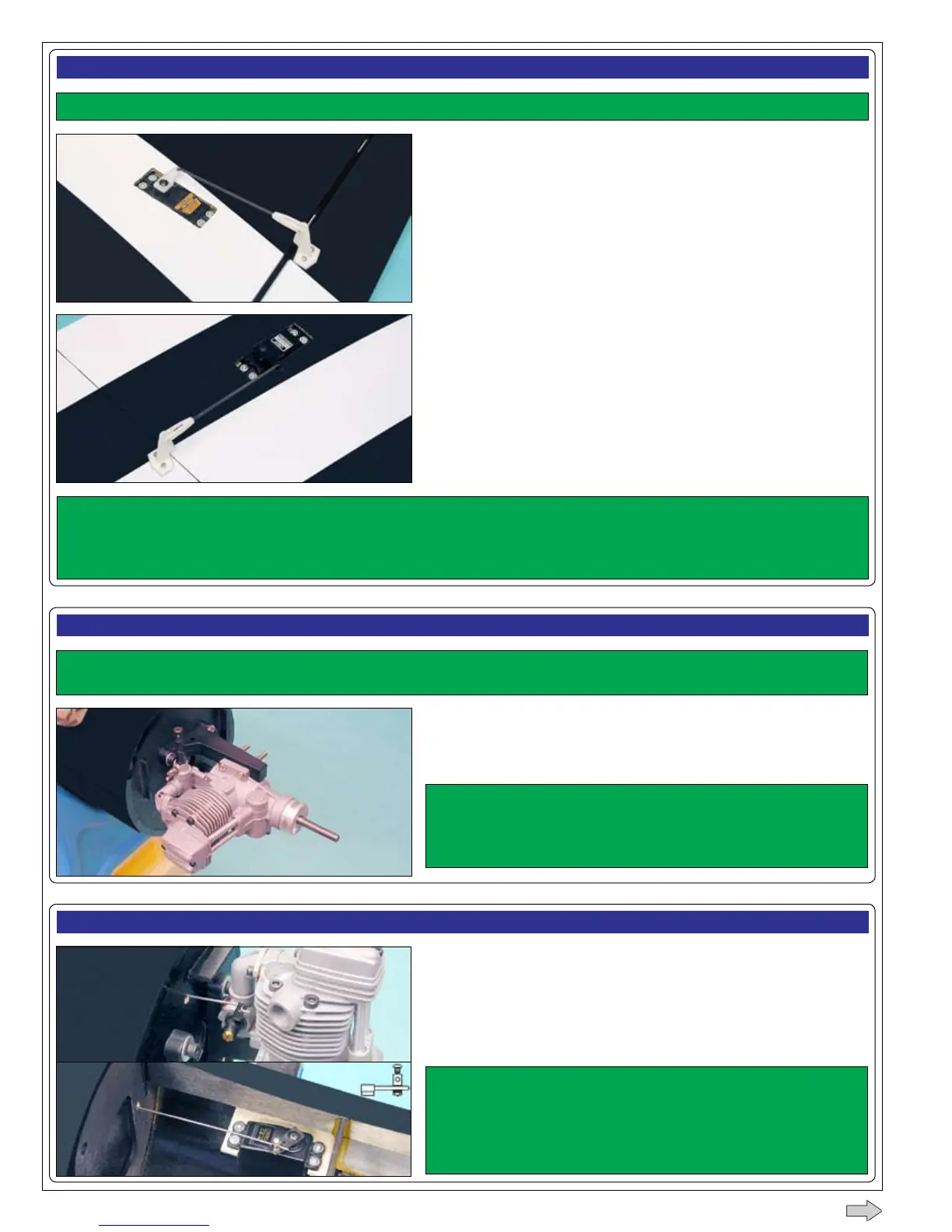
❑ Install the control linkages, using two threaded pushrod wires, two
control horns, two clevises and four wood screws provided. Each
control horn should be positioned approximately 4-1/4" (108mm) out from
the inboard edge of the aileron.
You may need to trim the servo mounting rails and/or the servo cutout in the outer wing panel to t your servos.
❑ Install one ap servo into each wing panel. Each servo output shaft
should be toward the trailing edge.
❑ Install the control linkages, using two threaded pushrod wires, two
control horns, two clevises and four wood screws provided. See the
important note below about positioning the ap control horns.
STEP 3: INSTALLING THE ENGINES
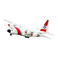
❑ Install one engine mount assembly and one engine onto each fuselage
boom, using the socket-cap screws, machine screws, washers and nuts
provided.
Each engine's drive washer should be 4-1/2" (114mm)
out from the rewall to line up correctly with the cowlings. Note that
the engines should be mounted on their sides, toward the right side of
the fuselage booms, too.
The engine mounting beams are adjustable to t the width of different sized engines. Make sure that when you
adjust the width of the mounting beams to t your engines, that you keep the mounting beams centered on the rewall.
STEP 4: INSTALLING THE THROTTLE CONTROL LINKAGE ASSEMBLIES
❑ Install your throttle servos and connect the throttle linkages, using the
pushrod wires and adjustable connectors provided.
☞
Install the adjustable connectors 1/2" (13mm) out from the center of
the servo arms to prevent the pushrods from interfering with the fuel tanks
when they're installed later. Cut away the excess servo arm material.
Make sure that you install and connect both throttle
linkages exactly the same way, so that both throttles will be synced as
closely as possible during ight.
Apply a drop of thin C/A to the nut on each adjustable
connector to keep them from coming loose during ight.
The control horn on the left wing panel should be positioned approximately 6" (152mm) out from the inboard edge of
the ap and the servo arm should point toward the wing tip. The control horn on the right wing panel should be positioned approximately
4-3/8" (111mm) out from the inboard edge of the ap and the servo arm should point toward the root end. Having both servo arms
point in the same direction will allow you to use a standard Y-Harness and still make both servos move the same direction.
CONTINUED