ICR-3241
2.6 Serial Interfaces and I/O Por t
The RS232 and RS485 ser ial interfaces together with the I/O interface are physically con-
nected to the 10-pin panel socket. All three interfaces are not isolated from the router. The
pinout of this conector is described in the tables below.
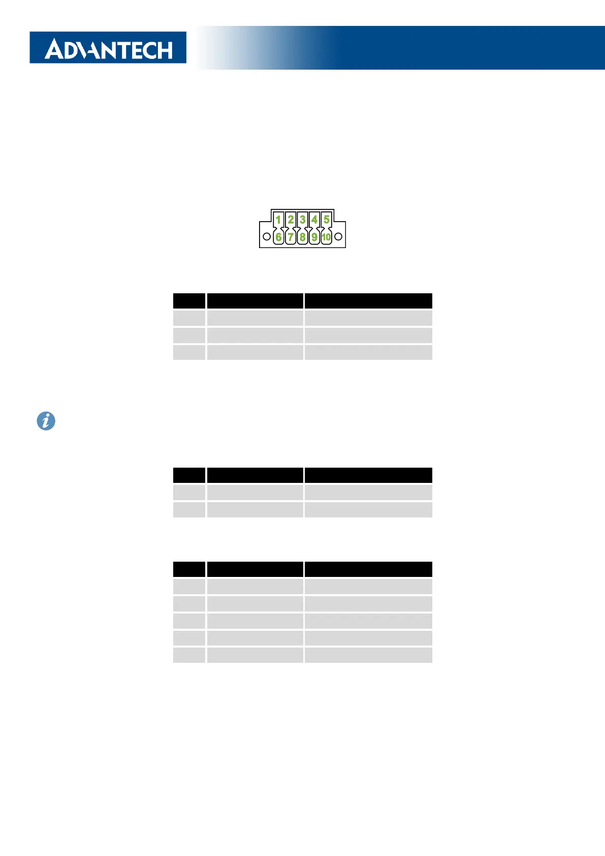
Figure 17: Serial + I/O connector
Pin Signal mark Description
1 B (+) IN/OUT
2 A (-) IN/OUT
3 GND GROUND
Table 8: Connection of RS485
We recommend connecting a termination resistor outside the router. Without termination re-
sistors, signal reflections off the unterminated end of the cable can cause data corr uption.
Termination resistors also reduce electrical noise sensitivity due to the lower impedance.
Pin Signal mark Description
4 BIN BINARY IN
5 BOUT BINARY OUT
Table 9: Connection of I/O
Pin Signal mark Description
6 RXD IN
7 CTS IN
8 GND GROUND
9 RTS OUT
10 TXD OUT
Table 10: Connection of RS232
The I/O user interface is designed for binary input processing and binary output control.
By default, the binary output is open, so it is not grounded. The maximum binary output load
is 36 V at 500 mA. The constant cur rent supplied by the binary input is 3 mA.
18
 Loading...