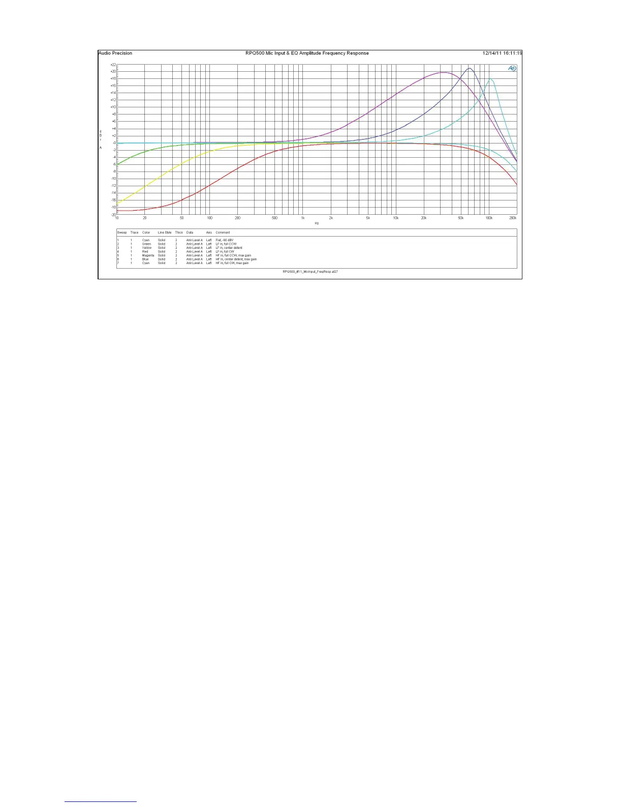
Figure 3: Amplitude frequency responses of mic input and filters.
reduce the Input Gain control correspondingly to avoid system overload.
Also remember, the energy and excitement generated during a perfor-
mance guarantees that it will always be louder than the rehearsal, so after
determining the gain during the sound-check it is a good idea to set the
Input Gain control one or two clicks lower for the performance to allow
yet a little more margin for headroom.
Line Input Mode
When using the Line Input mode the Input Gain control (ref. #10) is
bypassed and only the Output Gain control (ref. #11) is active. For ad-
ditional headroom, the signal is attenuated by 6 dB prior to the EQ/filter
section and the Output Gain control. The Output Gain control can either
apply up to +19 dB of gain in the full clockwise position or can attenuate
the signal as much as -64 dB just like a fader on a console. The output
line driver adds an additonal fixed gain of 6 dB following the Output
Gain control. The unity gain position can be found near the two o’clock
position.
Again, the LED level indicators (ref. #1) monitor the signal level at a
point in the signal path just prior to the input of the balanced output
amplifier. The green LED comes on in the presence of low-level signal;
the red LED turns-on when you are approaching signal overload or “clip-
ping.” The yellow LED varies in brightness between the two to indicate
 Loading...