English
36
13 TREBLE+/TREBLE- buttons (adjust trebles)
BASS+/BASS buttons (adjust basses)
14 button (On/Operational readiness)
Wall mounting
A Threadedbolt(2x)
B Mountingplate(2x)
C Countersunkscrew(4x)
D Dowel(4x)
First Use of the Device/Introduction
• Selectaproperplaceforthedevice.Adry,levelandslip
proof surface is suitable.
• Makesurethedeviceisventedsufciently!
• Removetheprotectivelmfromthedevice,ifpresent.
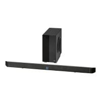
Wall mounting (Sound bar)
You can also mount the device to the wall.
CAUTION:
Make sure beforehand whether there are cables in the wall
which could be damaged!
NOTE: Check the reach of the cable!
To mount the device, make sure that an easily accessible
plug outlet is available within reach of the power cable.
The distance between the mountings for wall mounting is
618 mm.
• Holdthemountingplate(B)tothewallsothattheabove-
listed distance is kept horizontally and from the center of
the mounting plates.
• Markthefourpositionsofthemountingholeswithapen-
cil.
• Drillthemountingholes(diameter6mm).
• Stickthedowels(D)intotheboreholesandfastenthe
mounting plates to the wall with the countersunk screws
(C).
• Twistthethreadedbolts(A)intothebacksideofthe
sound bar so far that there is enough space between the
wall and the connection cable.
CAUTION: IMPORTANT!
For an optimal wall mounting we recommend the use
of connection cables with an angled connection. You
can obtain corresponding cables from the specialist
shop.
• Hangthedeviceintothemountingplates(B)withthe
screws (A). Check for stable support.
Establish a power supply and wireless subwoofer connec-
tion.
The wireless connection of the subwoofer is created automa-
tically.
• Setupthesubwooferinaradiusof5meterstothesound
bar.
• Makesurethegridvoltagecorrespondstothegureson
the rating plate.
• Plugthepowerplugofbothdevicesintoaproperly
installed protective wall socket.
• Now turnonthesubwooferbyswitchingthepowerswitch
on the back side of the device to the “ON” position.
The connection is established as soon as you turn on the
sound bar with the button (14).
NOTE:
The lithium cell in the battery compartment of the remote
control was possibly secured with a foil for the transport.
This prolongs the lifetime of the battery. Please remove this
foil before the first use to make the remote control ready
for operation.
• Openthebatterycompartmentontheundersideofthe
remote.
• Replacethecellwithabatteryofthesametype(CR
2025). Check that the polarity is correct (see battery com-
partment).
• Closethebatterycompartment.
If the remote is not in use for a lengthy period of time, please
remove the battery to prevent the battery acid from “leaking”.
WARNING:
• Donotexposethebatteriestointenseheat,suchas
sunlight, fire or similar. Danger of explosion!
• Keepbatteriesoutofthereachofchildren.Theyare
not toys.
• Donotforcebatteriesopen.
• Avoidcontactwithmetallicobjects.(Rings,nails,screws
etc.) Danger of short circuits!
• Shortcircuitsmayoverheatorevenignitebatteries.
This may lead to combustion.
• Whentransportingthebatteries,covertheterminalsfor
your safety with an adhesive strip.
• Ifabatteryleaks,donotrubtheuidintotheeyesor
the skin. If acid comes into contact with the eyes, rinse
with purified water and seek medical advice if symp-
toms persist.
NOTE:
• Oncetheconnectionisestablished,thecontrollight
of the subwoofer will light up. If no connection was
established,theLEDwillash. If no connection is made
within about 5 Minutes the LED goes out.
• Disconnectfrommainspowersupplyduringlonger
periods of non-use.
Insert/Replace Battery in Remote Control
• Turnonthesoundbarbyswitchingthepowerswitch
(5) on the backside of the device to the “ON” position.
 Loading...