Do you have a question about the AEG EDW750 and is the answer not in the manual?
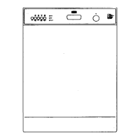
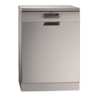
Illustrates various models of free-standing dishwashers with their control panels.
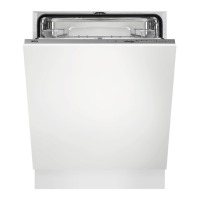
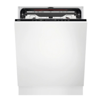
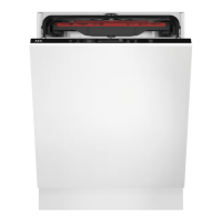
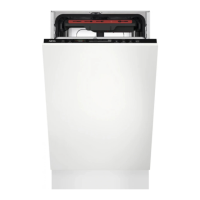
Showcases fully integrated dishwasher models and their respective control panel designs.
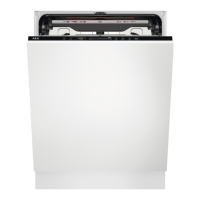
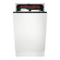
Details the visual appearance and control interfaces of built-in dishwasher models.
Diagrams showing LED and push button layouts for EDW1xxx-2G display boards.
Illustrations of LED and push button configurations for EDW3000 display boards.
Visual guide to LED and button placement on 'New Collection' display boards.
Instructions on how to access and exit the appliance's User Mode.
Guide to adjusting the water hardness setting on various dishwasher models.
Instructions for enabling or disabling the rinse aid dosing function.
How to enable or disable the end-of-cycle buzzer.
Comprehensive guide to service mode operations for the EDW500 model.
Detailed instructions for service mode operations on the EDW503 model.
Procedures for accessing and using the service mode on the EDW750 model.
Guide to entering and operating service mode for the EDW1850 dishwasher.
Steps to access service mode for EDW1950 and EDW1953 models.
How to enter and use the service mode for the EDW3510 touch version.
Procedures for accessing and navigating service mode on the EDW2500 Swiss.
Checking alarms, LED tests, and activating components for EDW1850/1950.
Activating and running the test programme on EDW1850/1950 models.
Procedure to enable or disable the additional rinse function.
Details for setting additional rinse on EDW750, EDW1850/1950, and EDW1953 Touch.
Steps to enter the diagnostics mode on the EDW2510 'Touch' dishwasher.
Navigating the diagnostics menu and understanding its functions.
How to check alarms and activate components in EDW2510 service mode.
Detailed list of component activation tests available in EDW2510 diagnostics.
Explanation of alarm code structure and how alarms are managed and displayed.
Description of alarms i10 (Water Tap Closed) and i11 (Dynamic Filling Issue).
Description of alarms i20 (Draining Problem) and i30 (Aqua Control).
Covers alarms i41-i44 related to analogue pressure sensor signal problems.
Covers alarms i51-i56 (Motor Problems) and i60-i61 (Heating Element Issues).
Details alarms i57-i5A (Voltage, Connection, Temperature) and i60-i61 (Heating).
Covers alarms i70 (Thermistor), i80-i81 (Door Opener), i90-iB0 (Configuration/Sensor).
Details alarms iC0-iC3 (Communication), iD0-iD1 (Tacho), and iE0 (Flow Controller).
Description of alarm iF0 for overfilling detected in the water level system.
Explanation of alarm iF1, indicating a high water level condition.
Overview of the redesigned hydraulic circuit and its components.
Highlights new components introduced in the dishwasher design and their functions.
Schematic representation of the dishwasher's water circuit and flow.
Technical specifications and connection diagram for the single-phase washing pump.
Details on the three-phase asynchronous inverter motor for the washing pump.
Technical data and characteristics of the synchronous motor drain pump.
Information on absorbed power, resistance, and safety thermostats for the heating element.
Main characteristics, frequency output, and tolerances of the analogue pressure switch.
Description of the flow meter's role in controlling water flow to spray arms.
Details on the separator and micro-switch within the flow meter.
Table of technical specifications, leakage rates, voltage, and resistance for the flow meter.
Notes on detergent dispenser operation, especially regarding manual closing and cooling.
Explanation of the mechanical latch and micro-switch for door lock security.
Objectives and application of the auto switch-off type ON/OFF switch.
Illustrates the operating principle of the auto switch-off mechanism.
Description of the Beam-on-Floor indicator, its colours, and time display.
Electrical schematic showing the connections and components of the EDW1xxx-2G model.
Electrical diagram for the EDW3000 with a single-phase motor.
Electrical diagram for the EDW3000 with a three-phase inverter motor.
Table detailing lead connections and correct values for checking AC motor components.
| Type | Freestanding |
|---|---|
| Washing Class | A |
| Drying Class | A |
| Delay Start | Yes |
| Dimensions (H x W x D) | 850 x 600 x 600 mm |
| Size | Full Size |