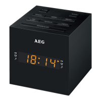
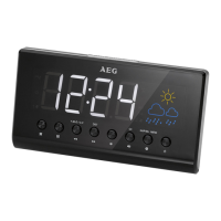
Overview of the Components
1 SNOOZE / SLEEP button
2 TIME SET / M + button
3 HOUR / TU − button
4 AL1 / VOL − button
5 ON / OFF button
6 FM / AM / AUX button
7 AL2 / VOL + button
8 MIN / TU + button
9 DISPLAY HIGH / LOW / OFF button
10 Indicator for radio switched on ( FM )
11 Indicator for activated alarm function 2 (
) ( Buzzer )
12 Indicator for activated alarm function 2 (
) ( Radio )
13 LED display
14 Indicator for activated alarm function 1 (
) ( Radio )
15 Indicator for activated alarm function 1 (
) ( Buzzer )
16 Indicator for radio switched on ( AM )
Back side ( not shown )
DC 5V power supply connection
AUX IN jack ( 3.5 mm stereo jack )
Dipole antenna
Bottom side ( not shown )
Battery compartment ( power reserve )
First Use of the Device / Introduction
• Select a proper place for the device. A dry, level and slip proof surface is suitable.
• Make sure the device is vented sufficiently!
• Remove the protective film from the device, if present.
Power supply
1. Make sure the grid voltage corresponds to the figures on the rating plate.
2. Plug the power supply unit into a properly installed protective contact socket.