76
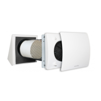
•Innerventilationunitmaterial:highquality,impactandUV-resistantABScolourRAL9010.
•Designfrontcoverremovableforcleaningwithouttheuseoftools.
•Easymaintenanceinstallationplate,foreasyaccesstotheheatexchangerfrominside
theroom.
•Anti-dustfilter,easilyremovableforwashingbytheuserwithouttools.
•Regenerativehoneycombsceramicheatexchanger.
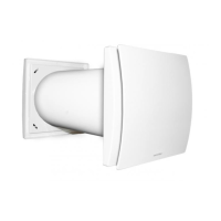
•Externalgrilleinhighquality,impactandUV-resistantABScolourRAL9010(STANDARD
version)orexternalhoodinaluminium,paintedinwhiteRAL9010,acousticallylined
(PROversion).
•Highefficiencyaerodynamicfanwith“winglet”bladestooptimisequietnessandefficiency.
•SinglephaseECreversibleBrushlessmotorwithintegralthermalprotection.
•Motormountedonhighqualityballbearings.
•Theunitisdoubleinsulated:noearthconnectionisrequired.
•Tricklespeedselectable.
•Boostmode.
•Free-cooling(Bypass)mode.
•IPX4degreeofprotection.
•Powersupply220Vto240V~50Hz.
The unit should operate continuously, and only stopped for maintenance or service.
When heat exchange is not useful (for example in mid-seasons when indoor and
outdoor temperatures are similar), or when heat exchange is not recommended
(for example with the option “summer free cooling”), it is recommended to set
the unit in “extract-only” or “intake-only” mode and NOT to switch it off.
TECHNICAL SPECIFICATIONS
Model Airflow m
3
/h Power W Weight Kg
QuantumHR100 10/15/25 1,2/1,7/2,6 2
QuantumHR150 20/40/60 1,4/2,3/3,8 4,2
QuantumHR100PRO 10/15/25 1,2/1,7/2,6 2,2
QuantumHR150PRO 20/40/60 1,4/2,3/3,8 4,5
STANDARD Externalgrilleinhighquality,impactandUV-resistantABScolourRAL9010.
PRO Externalhoodinaluminium,paintedinwhite(RAL9010),acousticallylined.
VERSIONS
OPERATION
Inbothversions,theunitpullsairoutfor70seconds,thenitpushesairinforthesametime.
Whenheatedairispulled(extracted)frominsidetheroom,itwarmsuptheheatexchanger;
whenthecoldairispushed(supplied)intheroom,itgetspreheated,recoveringmostof
S3switchactivatesthe“Freecooling“(Bypass)mode,whichstopsalternateowand
keepsthefanin“extract-only”or“intake-only”mode,toavoidtheheatexchangewhen
necessary.Tosettheextract-only”modeor“intake-only”,placetheintegraljumpersas
perfig.21A-21B).ThefrontcoverLEDindicateswhentheFreecoolingmodeison.
Anautomatic“Boost”modecanbeachievedthroughadedicatedswitchorroomsensors
likeSEN-HY,SEN-PIRorSEN-CO2,connectingsuchswitchinparalleltotheS2switch.
Wiringdiagramofoneunit:fig.19A.
Wiringdiagramwithambientsensors:fig.19Bandfig.19C.
Wiringdiagramoftwoormoreunits:fig.19D.
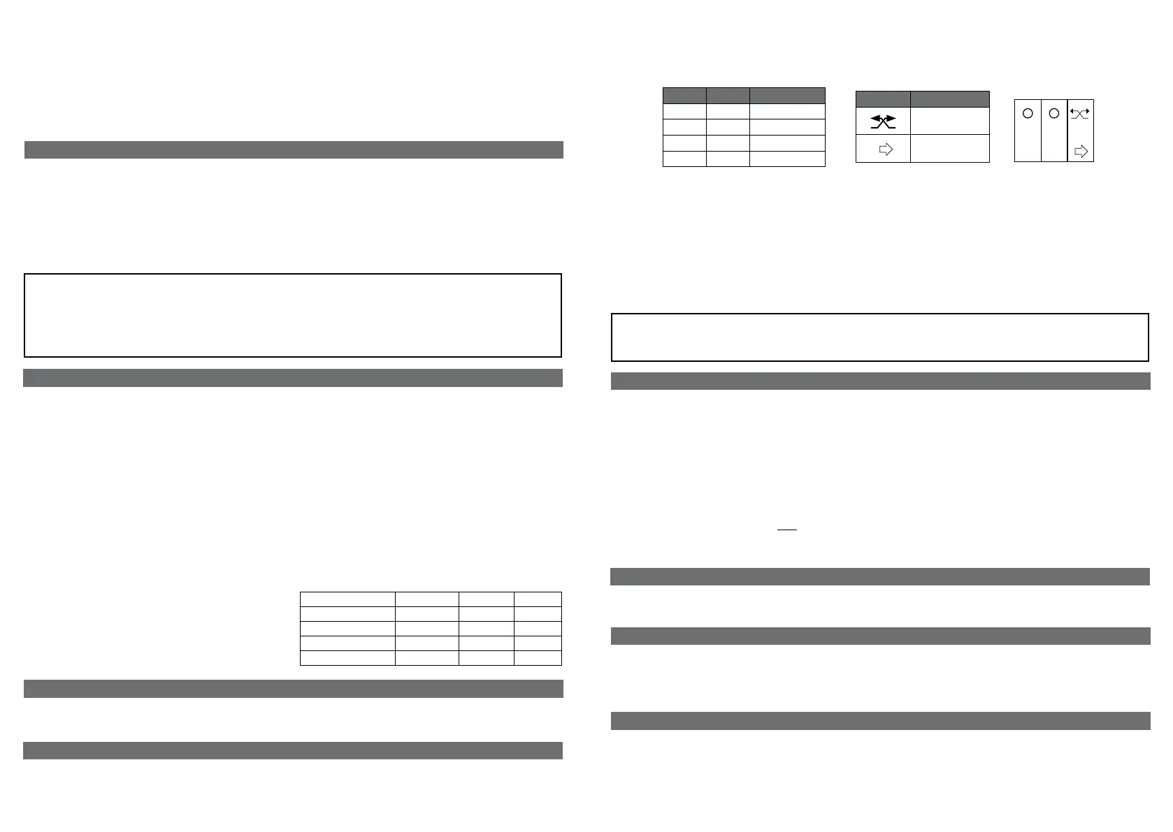
“S1” “S2” Operation
O O OFF
I O Speed1
O II Speed2
I II Speed3
“S3” Operation
Heatrecovery
(Alternateow)
Freecooling
S1 S2 S3
II
I
INTRODUCTION
QuantumHRisasinglealternateflowdecentralized(singlepoint)residentialheatrecovery
unit,alsocalled«push&pull»unit,designedtoensureadequateventilationinenclosed
environmentswithoutenergylosses.
Itisrecommendedthattwounitsareinstalledinpair:whenoneunitispulling,theother
ispushing.
Pairofunitscanbeinstalledinthesameroomorindifferentrooms(i.e.livingroomand
bedroom).Theunitissuitableforinstallationonanoutsidewall.
•Iftheenvironmentinwhichtheproductisinstalledalsohousesafuel-operatingdevice
(waterheater,methanestoveetc.,thatisnota“sealedchamber”type),itisessential
to ensure adequate air intake, to ensure good combustion and proper equipment
operation.
•Installtheproductsothattheimpellerisnotaccessiblefromtheairoutletsideas
verified by contact with the Test Finger (test probe “B” of the norm EN61032) in
compliancewiththecurrentsafetyregulations.
WARNING:
Ensure that the electric wiring to L and N is done correctly; an incorrect
connection will lead to malfunction or permanent damage of the fan
Whentheunitsareinstalledinpair,theymustbesynchronisedsothatwhenoneunitis
extracting,theotherissupplying,andviceversa.
Thisisachievedbysettingthededicatedjumper(fig.21A-21B)
RESET OF THE SYNCHRONISATION
OPTION1
Iftwoormoreunitsareconnectedunderthesamemainswitch,toresetthesynchronisation,
themainswitchmustbeswitchedfirstOFFandthenONtoreactivate(fig.38)
OPTION2
If two or more units are not connected under the same main switch, to reset the
synchronisation,pressatthesametimetheblackpinofeachunit(fig.40)foratleast
3seconds.
SyNCHRONISATION
Iftwoormoreunitsarecontrolledbymeansofthesamecontroller(CTRL-Sorsimilar),
theyalwaysoperateinasynchronisedway.Wiringdiagramasperfig.19D.
SyNCHRONISATION IN CASE OF INSTALLATION WITH CONTROLLER
IntergaljumpersetinpositionA(fig.21A)means“extract-only”mode.
IntergaljumpersetinpositionB(fig.21B)means“intake-only”mode.
Thejumperpositiondefinesboththeair-owdirectionwhentheunitisactivatedforthe
firsttime(forthesynchronisation)andtheair-owdirectionofthefree-coolingmode.
jUMPER POSITION
thermalenergywhichwouldbeotherwiselostintheventilationprocess.
Theunitrunsatthespeedselectedbyactivatingthetwo-positionswitches“S1”,“S2”
and“S3”oftheCTRL-S(accessoryfig.64).Thesamefunctionalitycanbeachievedwith
CTRL-Sorwith3two-positionswitches.
Maintenancecanbecarriedoutbytheuserasindicatedatpage28.
Servicemustbeperfmormedonlybytechnicallyqualifiedpersonnelinaccordancewith
localrulesandregulations.Makesurethatthemainssupplytotheunitisdisconnected
(page29).
Cleaningoftheheatexchangercanbeperformedfromoutsideaswell.
MAINTENANCE AND SERVICE
 Loading...