16
CC
CC
AA
AA
RR
RR
AA
AA
TT
TT
TT
TT
EE
EE
RR
RR
II
II
SS
SS
TT
TT
II
II
CC
CC
HH
HH
EE
EE
••
••
FF
FF
EE
EE
AA
AA
TT
TT
UU
UU
RR
RR
EE
EE
SS
SS
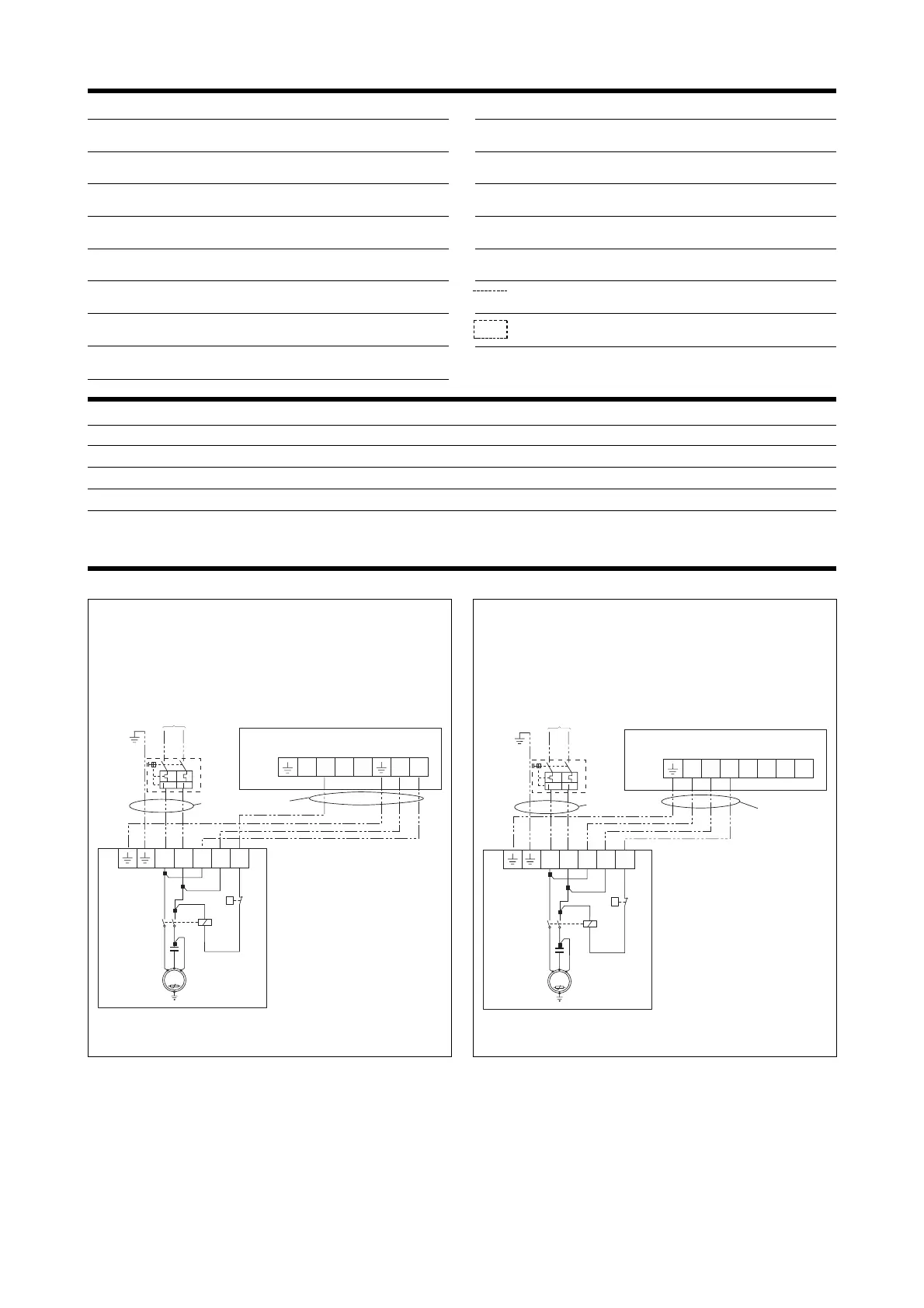
LEGENDA PER SCHEMI ELETTRICI • WIRING DIAGRAMS KEY
AP = Pressostato di alta
High pressure switch
CC = Contattore compressore
Compressor contactor
CMCP = Condensatore di marcia compressore
Compressor running capacitor
CP = Compressore
Compressor
IM = Interruttore di linea
Line switch
L = Fase d’alimentazione
Feeding phase
N = Neutro di alimentazione
Feeding neutral
PE = Collegamento di terra
Earth connection
PT = Protezione motore
Motor protector
RCS = Relè controllo sequenza fasi
Phase sequence control relay
RT = Relè termico
Thermal relay
TB = Morsettiera
Terminal board
Collegamenti da eseguire in loco
On-site wiring
Componenti non forniti
Components not supplied
DATI ELETTRICI • ELECTRICAL DATA
CWX 1207 1807 1807 T 2407 2407 T
IM [A] 10 16 6 16 6
SEZ. A [mm
2
] 1,5 2,5 1,5 4 1,5
SEZ. B [mm
2
] 1,5 1,5 1,5 1,5 1,5
SEZ. B
SEZ. A
CWX 1207 - 1087 - 2407
SCHEMI ELETTRICI • WIRING DIAGRAMS
Gli schemi elettrici sono soggetti ad aggiornamento; è opportuno fare riferimento allo schema elettrico allegato all’apparecchio.
Wiring diagrams may change for updating. It is therefore necessary to refer always to the wiring diagram inside the units.
SEZ. B
SEZ. A
 Loading...