EasyManua.ls Logo

AERMEC FCA 32 - FCA + PCT4 Wiring Diagrams

AERMEC FCA 32
64 pages
Print Icon
To Next Page IconTo Next Page
To Previous Page IconTo Previous Page
Loading...
60
V1
V2 V3
V1
V2
V3
V1
V2
V3
L
L
N
N
RO
BL
GR
RO
MA
SIT
PCT4
°
10
15
20
25
30
C
ON
OFF
PCT4
IG 2A
L
N
Sez. 1,5 mm
2
PE
1
~
230V 50Hz
FCA
Y1
Y2
N
N
L
LEX
M
V1
V2
V3
V4
VHA1
PCT4
°
10
15
20
25
30
C
ON
OFF
PCT4
IG 2A
L
N
Sez. 1,5 mm
2
PE
1
~
230V 50Hz
FCA
Y1
Y2
N
N
L
LEX
M
V1
V2
V3
V4
VHA1
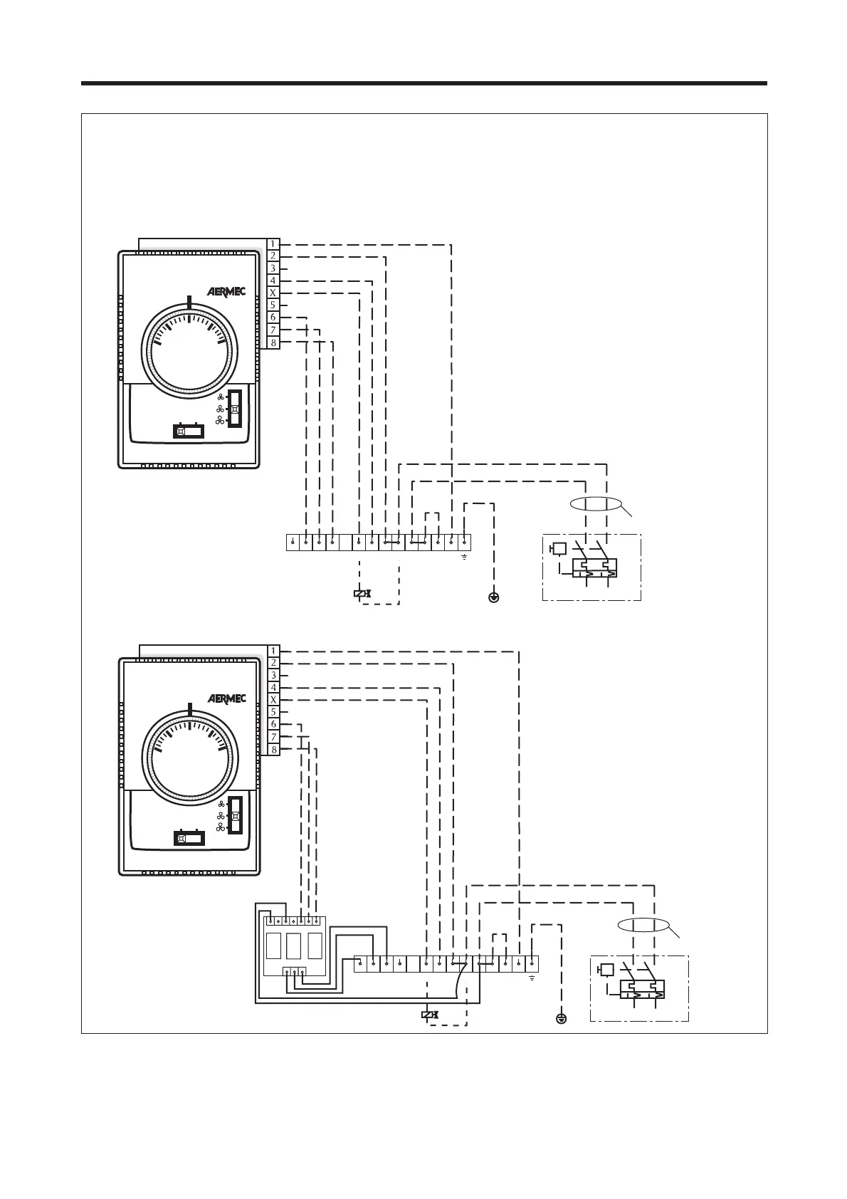
SCHEMI ELETTRICI • WIRING DIAGRAMS
FCA + PCT4
Con ventilazione sempre inserita (termostato in un impianto a
4 tubi e selezione caldo/freddo automatica).
With ventilation always on (thermostat in a four-pipe system
and automatic cold/hot selection).
Gli schemi elettrici sono soggetti ad aggiornamento; è opportuno fare riferimento allo schema elettrico allegato all' apparecchio.
Wiring diagrams may change for updating. It is therefore necessary to refer always to the wiring diagram inside the units.

Other manuals for AERMEC FCA 32

Related product manuals