30
English
1508 - 5138800_00
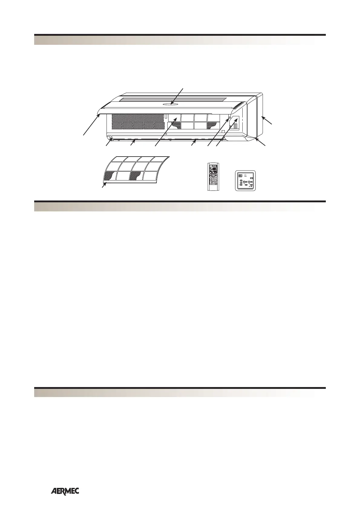
1 Front panel
2 Horizontal air discharge blades
3 Vertical air discharge blades
4
Air filter
5
Heat exchanger coil
6 Auxiliary emergency switch
7 Electric terminal connections
8 Front case
9 Frame
10 Display
D/EKDWKEEd^
FCW
TLW2
1
2
4
5 6
PFW2
10
9
8
3 3
7
^Z/Wd/KEK&KDWKEEd^
FRONT PANEL
The air intake is via the slots. Lifting the panel
gives access to the air filter and the internal
parts
RECEIVER
Infra red signal receiver for versions with
microprocessor controller
/^W>z
The display is mounted on the front panel, only
for versions with microprocessor controller. It
shows the fan speed, operating mode,
temperature, error messages, and timer
AIR FILTER
Washable air filter that can easily be removed
HEAT EXCHANGER COIL
Made of copper tubes with turbo lanced
aluminium fins
DISCHARGE AIR
The horizontal blades are:
- motorised for versions fitted with micropro-
cessor controller.
- manual for versions not fitted with micropro-
cessor controller
The vertical blades are manually adjustable to
allow optimal air discharge
hy/>/ZzDZ'Ez^t/d,
The auxiliary emergency switch, only for ver-
sions with microprocessor controller, allow
the fan coil unit to be turned on or off if the
wired control panel or remote control are not
operating
&E^^D>z
The fan assembly consists of an extremely com-
pact and quiet tangential type fan.
ϮͳtztdZs>s
The FCW_2V fan coil unit is supplied as
standard with a 2-way on/off water valve
and electro-thermal actuator controlled by
the fan coil controller , based on the water
temperature and the temperature of the
room
ϯͳtztdZs>s
The FCW_3V fan coil unit is supplied as
standard with a 2-way on/off water valve
and electro-thermal actuator controlled by
the fan coil controller , based on the water
temperature and the temperature of the
room
d>tϮZDKdKEdZK>;&tĂĐĐĞƐƐŽƌLJĨŽƌ
ǀĞƌƐŝŽŶƐǁŝƚŚŵŝĐƌŽƉƌŽĐĞƐƐŽƌĐŽŶƚƌŽůůĞƌͿ
ĐĐĞƐƐŽƌLJĞƐƐĞŶƚŝĂůĨŽƌƚŚĞĨĂŶĐŽŝůƵŶŝƚŽƉĞƌĂͲ
tion, as an alternative to the PFW2 wired
control panel.
The TLW2 remote control is provided loose
from the fan coil unit. One remote control
can control several fan coil units.
The remote control makes it possible to set all
the operating parameters of the unit. These
parameters are shown on a liquid crystal dis-
play making programming operations easier.
The remote control is supplied with a bracket
allowing it to be hung on the wall.
PFW2 WIRED CONTROL PANEL (FCW
ĂĐĐĞƐƐŽƌLJĨŽƌǀĞƌƐŝŽŶƐǁŝƚŚ ŵŝĐƌŽƉƌŽĐĞƐƐŽƌ
controller)
ĐĐĞƐƐŽƌLJĞƐƐĞŶƚŝĂůĨŽƌƚŚĞĨĂŶĐŽŝůƵŶŝƚŽƉĞƌĂͲ
tion, as alternative to the TLW2 remote con-
trol.
The wired control panel must be installed on
the wall and connected to the fan coil unit
with the cable provided loose.
The panel cable is 4 metres long.
The PFW2 makes it possible to set the main
operating parameters of the unit. These
parameters are shown on a liquid crystal dis-
play making programming operations easier.
A PFW2 wired control panel can control just
one fan coil unit.
Colour
Pantone Code: GRIS 1C
RAL Code: 9010
• sĞƌƐŝŽŶƐǁŝƚŚŽƵƚŵŝĐƌŽƉƌŽĐĞƐƐŽƌĐŽŶƚƌŽůůĞƌ
With or without water valve.
Versions without microprocessor controller
need to be combined with a control panel
(accessory) chosen from standard control
panels (compatible with the configuration of
the fan coil unit) or be combined with a ther-
mostat from the VMF system.
Warning! The VMF (VMF-E0 / VMF-E1) ther-
mostat can not be installed inside the fan
coil unit but the installer must provide an
adequate housing close to the fan coil unit
(such as a recessed electrical box on the wall
behind the fan).
sD&;sĂƌŝĂďůĞDƵůƚŝ&ůŽǁ^LJƐƚĞŵͿ
Management and control system of hydronic
systems for the air-conditioning, heating and
production of domestic hot water.
The VMF system allows complete control of
every component of a hydronic system both
locally and centrally and, communicating
between the various components of the sys-
tem, manages the performance without ever
neglecting the end user's request of comfort,
but reaching it as efficiently as possible with
energy saving.
If you add the advantages deriving from such
an innovative control to the flexibility of a
hydronic system, you get a more efficient and
effective alternative to the variable refriger-
ant flow systems (VRF).
The VMF system is extremely flexible, enough
to allow various steps of control and manage-
ment, expandable at different moments:
1) Control of a single fan coil unit.
2) Control of a microzone (one MASTER fan
coil unit and a maximum of 5 SLAVE fan coils
units).
3) Control of multi independent zones system
(one MASTER fan coil unit and a maximum of
'EZ>/E&KZDd/KE
 Loading...