28
English
AGLL10/20NFJ 07/11_4528571_00
M2 L: power supply input of the Voltage
card: 230 Vac, current 10 A
M1 N: power supply input of the
Voltage card: 230 Vac, current 10 A
M3 GND: ground reference
M4 AUX/RE: electric resistor control
output
Voltage:230 Vac, current 10 A
M5 Neutral reference for the AUX/RE
and MA output Voltage: 230 Vac,
current 7 A
M6 MA: fin motor control output
Voltage: 230 Vac, current 5 A
M7 Y2: water valve control output
Voltage: 230 Vac, current 5 A
M8 Y1: water valve control output
Voltage: 230 Vac, current 5 A
M9 Neutral reference for output Y1, Y2
Voltage: 230 Vac, current 10 A
M10 Neutral reference for output V1, V2
V3 Voltage: 230 Vac, current 10 A
M11 V3: maximum speed output
Voltage: 230 Vac, current 5 A
M12 V2: average speed output Voltage:
230 Vac, current 5 A
M13 V1: minimum speed output
Voltage: 230 Vac, current 5 A
M14 Support input, not connected
M26 Service control board
M22 Control board for connection to
the receiver
CN2 SW: water probe NTC 10Kohm
CN1 SA: air probe NTC 10Kohm
CN3 SC: auxiliary water probe NTC
10Kohm
M15, M16 SR: electric resistor tempera-
ture probe NTC 4Kohm 200°C
M17 Out 0-10V: Inverter reference
Voltage: 10 Vdc, current 10 mA
M18 GND of the inverter reference
Voltage: 10 Vdc, current 10 mA
M19 Out 0-10V Voltage: 10 Vdc, cur-
rent 10 mA
M20 GND Voltage: 10 Vdc, current
10 mA
M21 Fault inverter reading input
Voltage: 10 Vdc, current 10 mA
M25 Connector for expansions
M27,M28 CC: Condensate discharge
motor fault input Voltage: 5 Vdc,
current 0.5 mA
Pauses 2.: Resistor protection fuse
Delayed 10A fuse
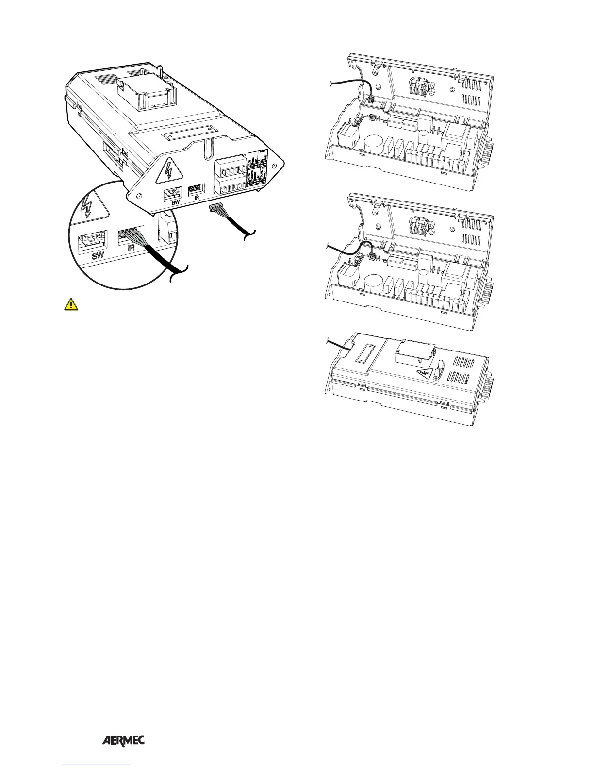
CONNECTOR CONNECTION TO THE CONTROL BOARD
IR CONNECTION (THERMOSTAT RECEIVER) 4-PIPE PROBE CONNECTOR CONNECTION
The display card will physically connect to the GLLI_N
control box through a 4-pole cable as shown above