6. TECHNICAL DATA
6.1. STANDARD VERSION ° - L SIZE 0500-0550-0600-0650-0700-0800-0900-1000-1250-1400
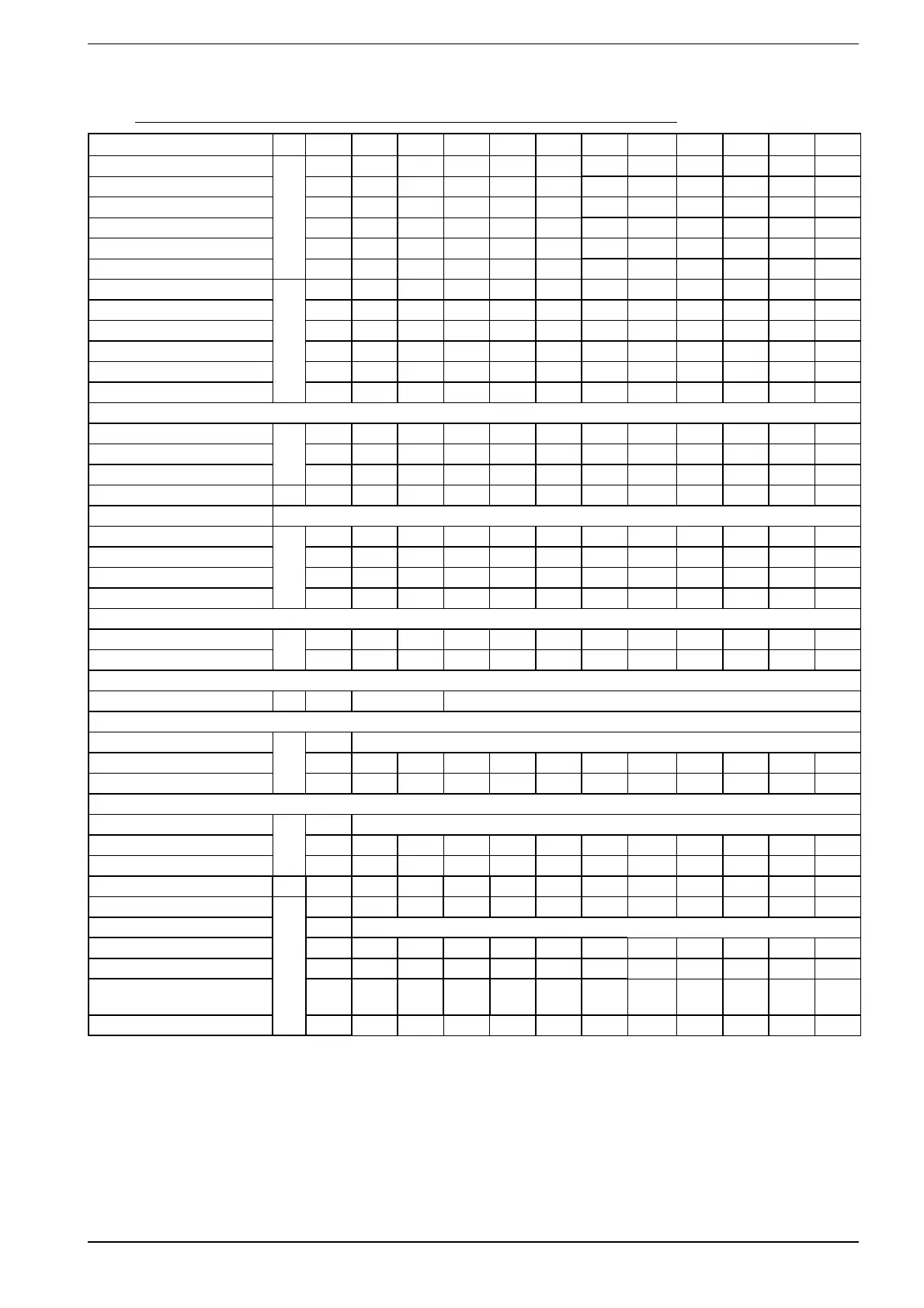
Mod. NXW vers U.M. 0500 0550 0600 0650 0700 0750 0800 0900 1000 1250 1400
Cooling capacity [1]
° - L
kW 112 121 149 167 189 223 258 292 326 355 385
Total input power kW 22.2 23.9 29.5 32.9 37.3 43.6 50.4 57.8 64.5 70.3 76.1
Evaporator water flow rate l/h 19264 20812 25628 28758 32458 38392 44325 50188 56050 61097 66142
Evaporator pressure drop kPa 30 35 32 40 43 47 49 55 35 36 36
Condenser water flow rate l/h 22892 24718 30449 34141 38548 45511 52565 59629 66594 72590 78585
Pressure drop at condenser kPa 25 29 29 37 37 45 60 38 29 34 36
Heating capacity [2]
° - L
kW 119 129 161 181 205 242 279 318 356 388 419
Total input power kW 26.5 28.6 35.7 40.0 45.5 53.5 61.8 70.4 79.2 86.2 93.2
Condenser water flow rate l/h 20468 22188 27692 31215 35195 41595 47995 54638 61281 66656 72030
Pressure drop at condenser kPa 20 23 24 31 31 38 50 32 25 29 30
Evaporator water flow rate l/h 16138 17515 21859 24681 27763 32850 37904 43140 48340 52574 56807
Evaporator pressure drop kPa 21 25 23 29 31 34 36 41 26 27 27
ENERGY INDEXES
EER
° - L
W/W 5.05 5.06 5.05 5.08 5.06 5.12 5.11 5.05 5.05 5.05 5.05
EEEC --- A A A A A A A A A A A
ESEER W/W 6.01 6.02 6.01 6.04 6.02 6.05 6.03 6.02 6.06 6.05 6.06
COP ° - L W/W 4.49 4.51 4.51 4.54 4.50 4.52 4.52 4.51 4.50 4.50 4.50
ELECTRICAL DATA 400V 3 50Hz
Input current (cooling)
° - L
A
48.3 50.6 58.4 63 86 94 102 120 138 140 143
Input current (heating) A 54 57 66 72 94 105 115 135 154 160 165
Maximum current A 75 80 96 107 122 146 169 193 217 231 248
Starting current A 240 245 227 238 289 319 341 398 422 490 504
CHARGE
Refrigerant R410A(C1/C2) [*]
° - L
kg
6.0/6.0 6.0/6.0 7.8/7.8 7.8/7.8 9.0/9.0 10.0/10.0 12.0/12.0 16.0/16.0 24.0/24.0 25.0/25.0 27.0/27.0
Oil Circuit (C1/C2) dm
3
6.6/3.6 6.6/3.6 6.6/6.6 6.6/6.6 7.2/7.2 13.4/7.2 13.4/13.4 13.4/13.4 13.4/13.4 13.9/13.9 13.9/13.9
COMPRESSOR (SCROLL)
No. of compressors/circuits ° - L no./no. 3/2 4/2
EVAPORATOR (plates)
Quantity
° - L
no. 1
Water content L 7.0 7.0 9.5 9.5 10.4 12.3 14.8 16.7 30.2 32.9 37.4
Victaulic water connections diam 2"1/2 2"1/2 2"1/2 2"1/2 2"1/2 2"1/2 2"1/2 2"1/2 3" 3" 3"
CONDENSER (plates)
Quantity
° - L
no. 1
Water content L 9.5 9.5 12.3 12.3 14.8 16.7 16.7 30.2 45.5 45.5 49.9
Victaulic water connections diam 2"1/2 2"1/2 2"1/2 2"1/2 2"1/2 2"1/2 2"1/2 2"1/2 3" 3" 3"
HEAT RECOVERY (PLATE HEAT) Vers. U.M
Recovered heating capacity
° - L
(1) kW 120 130 162 183 206 244 281 320 359 390 422
Quantity no. 1
Total input power (1) kW 28.9 31.1 38.9 43.5 49.5 58.3 67.3 76.6 86.2 93.8 101.5
Water flow rate recovery (1) l/h 20610 22340 27890 31430 35440 41890 48330 55020 61710 67120 72530
Pressure drops of the recovery
exchanger
(1) kPa 20 23 24 31 31 38 51 32 25 29 30
Water connections (VICTAULIC) diam 2"1/2 2"1/2 2"1/2 2"1/2 2"1/2 2"1/2 2"1/2 2"1/2 3" 3" 3"
In cooling operation [1]
processed water temperature 7°C
Condenser inlet water temperature 30°C
DT 5°C
In heating operation [2]
processed water temperature 45°C
Evaporator inlet water temperature 10°C
DT 5°C
Reference data
[*] This data is subject to variations.
Desuperheater
Water temperature to desuperheater 45°/50°C
Water temperature condenser 30°C/35°C
Water temperature evaporator 12°C/7°C
Total recovery
Water temperature to total recovery 45°/50°C
Water temperature to evaporator 12°/7°C
13
INXWPY. 1004. 4438805_00