Jl. THERMOSTAT CABLE |NSTALLATION |L INSTA_C[_N DEL CABLE DEL TERMOSTATO
The thermostat for this cooler is connected to the cooler by
means of a 6 conductor thermostat cable (not provided).
Type CL2, 18 or 20 gauge, UL listed thermostat wire is
recommended.
A_
Route one end of the thermostat cable (9) through the
1/2'_hole in the corner post on the left side ofthe access
door and then through the 1/2_'hole in the left end of
the control box.
B, Insert the individual conductors of the thermostat ;wire
(9) into the terminal block connections on the right side
of the printed circuit board (6). Connect colored wires
to terminals asfollows: white to '_C_',brown to _H_,red
to _'L_,green to '_P_,yellow to "D_,and blue to _'R_%Tighten
screws.
C_
Install strain relief bushings (7) over the thermostat
cable into the 1/2°holes in thecorner post and control
box, allowing aslight amount of "slack',do not stretch
the thermostat cable tight. Replace the control box
cover - tighten the four screws.
D, Select a location for the thermostat
1. Mount the thermostat about 5 feet above the floor,
2, Mount the thermostat on a partitioning wall, not an
outside wail.
3_ Do not mount it near sources of heat,
4, Do not mount it in the direct draft of cooler air
registers_
5 Avoid dead air spaceswhich have titt[e air circulation,
E. Install the thermostat usingthe "Mounting Instructions
for Thermostat" furnished with the cooler,
8
Eltermostato est_ conectado al enfriador pot medio de
un a[ambre piano de 6 conductores tipo telefono de 66
pies de largo (9) induido en Jacaja,
A,
Guie una punta de[cable de termostato (9) aitrav6s de[
aguiero de 1/2_en el poste de el [ado izquierdo de [a
puerla de acceso y despu6s altrav6s del agujero de
1/2 °de [a caja de controJes.
B. [nserte el conectador en el socket proveido en eI tado
izquierdo de[ circuito impreso (6)en la caia de contro[es.
C_
[nstaJee/sujeta cable (7) sobre el cable yen los aguieros
de 1/2 _ en la esquina de[ gabinete yen ]a caja de
contro[es. Deiando una prequena cantidad de cable,
no estire et cable det termostato. Ponga la tapadera de
[a caja de[ control con los cuatro tornillos.
D. Seleccione el tugar para el termostato.
1. MonteM a 5 pies de[ piso.
2, [nsta[ee[ termostato en u_a pared interior no en una
pared que de al exterior.
3. No monte el termostato cerca de una fuente de calor
4_ No Io monte en ta corriente de aire directa de [as
parri[las de[ enfriador.
5. Evite espacios muertos de aire que tengan poquita
circulaci6n.
E. Instate el termostato usando las "lnstrucciones para
montar et termostato" proveidas con el enfriador.
7 6
4 3 2 1
9 5
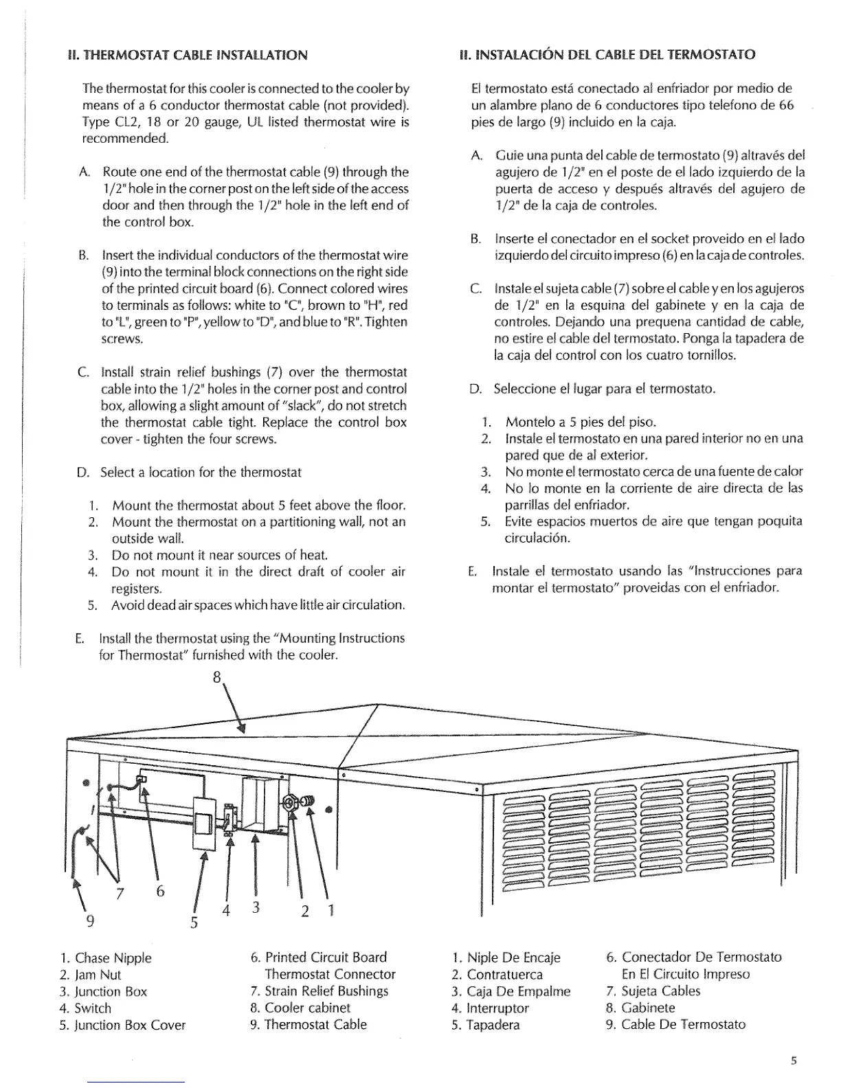
1. Chase Nipple
2, Jam Nut
3. Junction Box
4 Switch
5, junction Box Cover
6, Printed Circuit Board
Thermostat Connector
7, Strain Relief Bushings
8, Cooler cabinet
9. Thermostat Cable
/
1. Niple De Encaje
2. Contratuerca
3. Caja De Empalme
4, lnterruptor
5. Tapadera
6. Conectador De Termostato
En ElCircuit() tmpreso
7. Sujeta Cables
8. Gabinete
9. Cable De Termostato
 Loading...