Note - alignment of the temperature sensor
The temperature sensor is attached to the bottom of the radiator in a clip. If, due
to an placement of the device in a niche or corner, the room temperature and
the measured temperature is influenced, the sensor can be removed from the
clip. The distance to the radiator can be increased by turning the connection
cable of the sensor. The best way to correct the temperature is the menu
„temperature correction“ .
Smart Start (adaptive start control)
With this function, the desired room temperature is reached already at the start
time of the program. This means that the heater is already heating before the set
start time. This is not a malfunction! Smart Start can only be used in program
mode. You can deactivate Smart Start in the menu item "Programs". When
Smart Start is deactivated, the electric radiator starts heating when the preset
start time is reached.
Learning phase: In order to reach the target temperature exactly at the start time
of each programmed time frame, your FlexiSmart performs a learning phase in
the first seven days. During this time, heating is always started 15 minutes before
the set start time (in every single time window).
As a result, the FlexiSmart controller learns how fast or slow heating takes place
in the room and adjusts the „smart start time“ of heating. After the learning
phase, the FlexiSmart controller decides when to start heating up. Your rooms
will be heated up as effectively as possible.
Switch daylight saving time to standard time
The FlexiSmart controller does not have an automatic changeover between
daylight saving time to standard time. You must change the time manually in the
"Set the time" menu.
Exception: If the FlexiSmart controller is connected to an internet module, an
automatic changeover takes place between daylight saving time to standard
time.
+
-
Manual on assembly of wall bracket
Only the wall bracket supplied may be used for wall mounting! The latest
regulations according to VDE 0100 part 701 must be complied with for the
installation and operation in damp rooms.
The device may not be mounted directly under a wall socket. In order to avoid
excessive heat radiation upon the wall socket, a certain safety distance must also
be taken into account between the radiator and the wall socket. This distance is
largely determined by the material quality and heat resistance of the locally
installed socket and therefore can not be assessed by us. We assume no liability
for improper handling and possible damages resulting from this. In case of
doubt, consult a specialist before installation. Suitable screws and dowels must
be used depending on the type and condition of the wall material. When
positioning the wall bracket and the heater, please always observe the stipulated
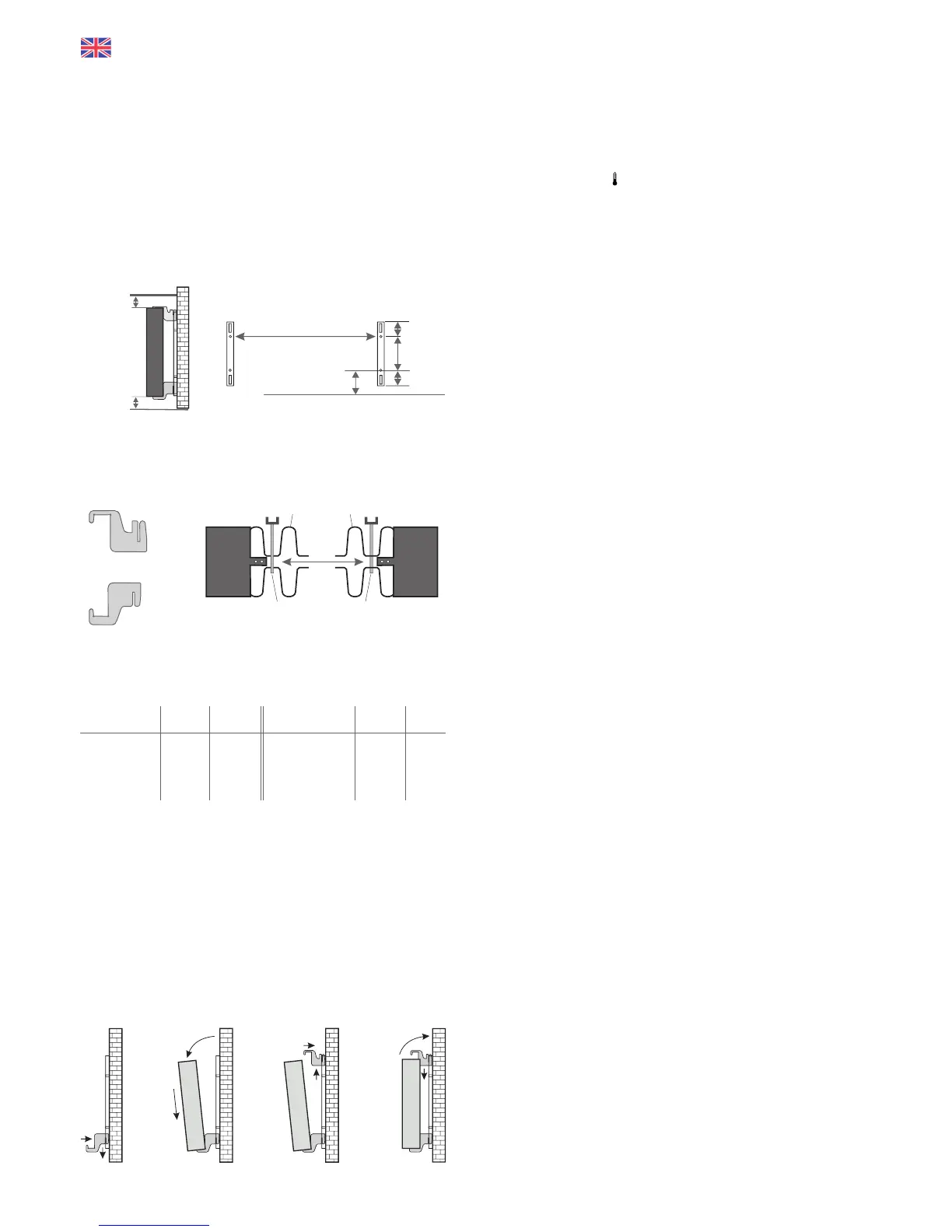
minimum distances (see the following figures).
All radiators have four temperature-resistant holders, which guarantee optimum
fixing of the heater. Please note the correct hanging position of the upper
(marking 1) and lower (marking 2) holders on the heater (see following figures).
With the type-specific dimension table, you always obtain the correct
positioning for the U-rails and the holders for the correct mounting and fixing of
the radiator.
For the assembly please perform the following steps:
1. The two U-rails must be fixed to the wall whilst observing the minimum
distances and depending on the type-specific X / Y-dimension.
2. The two holders marked with the marking 2 are to be inserted into the U-rails
at the bottom.
3. Following this the radiator is hooked into the lower holders and tilted forward
at an angle. Hold the radiator while doing so!
4. The two holders marked with the marking 1 are to be inserted into the U-rails
at the top and temporarily pulled up.
5. Finally, place the radiator in a vertical position and press the upper holders
down until the heater is completely fixed in place.
Fig. 2
10 cm
8 cm
Dim X
Dim Y
190 mm
90 mm
90 mm
Fig. 1
Aachment dimensions
X
1
2
Above
Below
Slat Slat
holder
holder
Radiator type Dim X Dim Y
in mm in mm
MINI 650 232 405
COMPACT 1300 466 405
MIDI 1950 766 405
Radiator type Dim X Dim Y
in mm in mm
MAXI 2450 1066 405
SLIM 1200 766 120
SLIM 1600 1066 120
SLIM TALL 1600 232 1040
1
2
2
1
2
1
2
2
1
2
1
2
2
1
11
 Loading...