EasyManua.ls Logo

AeroFoam T-45 - User Manual

AeroFoam T-45
27 pages
Print Icon
To Next Page IconTo Next Page
Loading...
T-45
1/6.26th Scale
Length 69 inches Fuselage only (1753mm) (74.99 inches 1904mm with Pitot tube)
Wing Span 59.1 inches (1501 mm)
Weight RTF minus Fuel 16lbs (with AUT full)
Suggested Engine Size: 60n ~ 80n (8kg ~10kg) Perfect for our ACEx60 to ACEx80
CG 178mm (7 inches) from leading edge at root of wing to fuselage.
Ailerons Low 10mm / .40 inch Mid 12 / .47 inch High 14mm /.55 inch.
Flaps TakeOff 24mm Landing 40mm
Elevator low rate 19mm / .75 inch Mid 23mm / .90 inch High 26mm / 1.02inch.
Rudder Low 26mm / 1 inch High 38mm / 1.5 inch
Airbrake low 50mm high 85mm (do not operate at high Speed)
Question and Answer IconNeed help?

Do you have a question about the AeroFoam T-45 and is the answer not in the manual?

Summary

Aircraft Overview and Specifications

Key Aircraft Specifications

Details on scale, length, wingspan, weight, and suggested engine size.

Control Surface and CG Settings

Recommended throws for control surfaces and the Center of Gravity (CG) location.

Kit Contents and Components

Identification and listing of included aircraft parts and hardware.

Servo and Electronic Setup

Servo Specifications and Caution

Details on servo types and critical warnings for initial servo connection and setup.

EBEC and Power System

Information on the installed EBEC for battery inputs and outputs, and power distribution.

Servo Placement Diagram

Visual guide showing the location and type of servos for each control surface.

Nose Section Assembly

Nose Section Servo Connections

Guidance on passing and connecting servo leads from the nose section to the fuselage.

Attaching Nose Section

Instructions for joining the nose section to the main fuselage using bolts.

Fuel Tank Installation and Setup

Fuel Tank Capacity and Configuration

Details on the 1600cc main fuel tank and options for smoke systems.

Fuel Line Best Practices

Recommendations for securing fuel lines with barbs and safety wires for reliability.

Tank Mounting and Access

Instructions for removing the tank and securing it with a wood stopper.

Elevator and Rudder Installation

Elevator Servo and Travel Setup

Installing the elevator servo, setting neutral point, and configuring elevator travel rates.

Vertical Fin and Rudder Installation

Attaching the vertical fin and rudder, and setting rudder control throws.

Aileron, Flap, and Slat Setup

Aileron Control Rod Configuration

Installing aileron control rods, detailing options for optimal mechanical advantage.

Flaps and Leading Edge Slats Setup

Installing control rods for flaps and slats, setting synchronized travel for both.

Turbine and Smoke System Installation

Turbine Mounting and Gap Adjustment

Instructions for installing the turbine, ensuring correct mounting and gap clearances.

Smoke System Options and Installation

Information on available smoke kits and installation guidance for the smoke pump and injector.

Center of Gravity (CG) Check

CG Measurement Procedure

Detailed steps on how to manually check and confirm the aircraft's Center of Gravity.

Retract and Brake Controller System

Retract Controller Functionality

Explanation of the installed retract controller for timing gear and doors.

AG63 Gyro Brake Controller Overview

Introduction to the AG63 module, its benefits for steering and braking.

AG63 Installation and Setup

Step-by-step guide for installing and configuring the AG63 gyro brake controller.

AG63 Operation and Notes

Important notes on using the AG63, including brake function, steering setup, and trim.

Flying Notes and Recommendations

Flight Operations and Trim

Advice on CG, power settings, landings, and general flight handling.

Landing Gear and Strut Maintenance

Notes on landing gear doors, strut bars, tail hook, and screw maintenance.

Overview

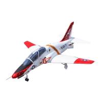
This document describes the Aerofoam T-45, a 1/6.26th scale RC jet, and its associated components, including specifications, assembly instructions, and operational notes.

Aerofoam T-45 RC Jet

Function Description:

The Aerofoam T-45 is a highly detailed, 1/6.26th scale remote-controlled jet designed for turbine power. It is intended for experienced RC pilots and features a realistic design and advanced control systems. The jet is designed for flight with a turbine engine, offering scale-like performance and maneuverability. It incorporates various control surfaces such as ailerons, flaps, elevator, rudder, and speed brakes, all operated by servos. The model also includes retractable landing gear with steering and electromagnetic brakes for enhanced ground handling.

Important Technical Specifications:

  • Scale: 1/6.26th
  • Length: 69 inches (1753mm) fuselage only; 74.99 inches (1904mm) with Pitot tube
  • Wing Span: 59.1 inches (1501mm)
  • Weight (RTF minus fuel): 16 lbs (with AUT full)
  • Suggested Engine Size: 60n ~ 80n (8kg ~ 10kg), compatible with ACEx60 to ACEx80 turbines.
  • Servos:
    • 1x 45g servo for Elevator
    • 5x 25g servos for Aileron, Flaps, and Rudder
    • 4x 17g servos for Slats
    • 6x 12g servos for Landing Gear doors, speed brakes, and Steering
    • All servos operate at 6.0V MAX.
  • Main Tank Capacity: 1600cc / 54oz (two included)
  • Header Tank / UAT Capacity: 4oz
  • Receiver Battery: 3S 2200 or 2x 3S 1600-1800mAh required for Receiver (not included)
  • Ready-to-Fly Weight (no fuel, UAT full): 7.3kg / 16 lbs (PNP version)
  • Center of Gravity (CG): 178mm (7 inches) from the leading edge at the root of the wing to the fuselage.
  • Control Surface Travel Rates:
    • Ailerons: Low 10mm / .40 inch, Mid 12mm / .47 inch, High 14mm / .55 inch
    • Flaps: TakeOff 24mm, Landing 40mm
    • Elevator: Low 19mm / .75 inch, Mid 23mm / .90 inch, High 26mm / 1.02 inch
    • Rudder: Low 26mm / 1 inch, High 38mm / 1.5 inch
    • Airbrake: Low 50mm, High 85mm (do not operate at high speed)

Usage Features:

Assembly and Setup:

  • Kit Contents: The kit includes the nose cone, fuselage/body, wings, canopy/cockpit, elevators, vertical fin, main wing spar, vertical fin spar, Pitot tube, nose hardware, mounting hardware, and fuel tank formers. Pushrods are not factory installed and must be installed by the customer.
  • Nose Section: Four servo leads (gear retract, LED for landing light, rudder/steering, gear door) connect to matching cables in the fuselage. Ensure correct power wire matching (two-wire vs. three-wire cables). The nose section is secured to the fuselage with four Metric 4x50 screws and washers. Removing the receiver tray can ease installation.
  • Fuel Tanks: Two 1600cc main tanks are included. A smoke pump can be installed in the top tank position. Fuel lines come pre-installed with zip ties, but for best practice, fuel barbs and safety wires are recommended to prevent spills and air bubbles. The receiver tray in the nose must be removed to access the UAT and fuel connections. The main tank is secured with a three-piece wood stopper assembled with CyA.
  • Elevator: A single 45g servo controls the elevator via a push-pull rod system. The servo is located in the tail on the left side, accessible via a cover with two Phillips screws. The servo horn should be at 90 degrees when the elevator is in the neutral position, aligning with the airfoil shape on the fuselage.
  • Vertical Fin / Rudder: The vertical fin is installed by inserting a carbon spar into the fuselage. The rudder then slots into the fuselage, connecting to a pre-installed 25g servo.
  • Ailerons: Servos and control rods are pre-installed. For optimal resolution and torque, use the third screw hole from the top on the servo horn and the top hole on the control surface.
  • Flaps: Servos are pre-installed. Install the control rod on the second hole from the top of both the servo arm and the control horn for better mechanical leverage.
  • Leading Edge Flaps / Slats: Pre-installed with servos and control rods. Travel throw must be set to activate simultaneously with the main flaps. Max deployment is about .75 inch (19mm). For takeoff, 9mm (.35 inch) slat deployment and 19mm (.75 inch) full flap deployment are suggested.
  • Turbine Installation: For ACEx80 turbines, mounting holes are pre-drilled. Ensure a 1 to 1.5-inch gap between the rear tail cone of the turbine and the start of the actual pipe (not the bellmouth).
  • Smoke System (Optional, Sold Separately): Various kits (brushed/brushless pumps, injectors) are available. The smoke pump can be located in the engine compartment, and the smoke tube routed between tailpipe layers, exiting at the tail. Ensure the injector sprays into the exhaust to promote burning.
  • Retract and Brake Controller: Pre-installed. If unplugging, label connections. One servo lead connects to the receiver for retracts, with the controller managing gear and door timing. A button on the controller cycles the landing gear.
  • AG63 Gyro Assisted Brake Controller: This system stabilizes steering and modulates left/right brakes digitally for straight tracking during taxi, takeoff, and landing. It prevents uneven braking, antilock/slip control, and reduces cartwheeling by automatically reducing steering input. It reduces wear on landing gear components and tires.
    • Installation: Secure with double-sided adhesive tape in a fixed position, away from turbine heat/suction. It can be installed in various orientations (four arrows on the unit, or upside-down).
    • Setup/Configuration:
      1. Power on: Red and blue lights flash quickly (initialization). Do not move the airplane or joysticks.
      2. Blue light on/flashing: Initialization complete. Test nose wheel steering direction; reverse if incorrect.
      3. Set aircraft level. Move steering joystick left full rudder, then quickly cycle the brakes switch on/off at least 3 times until red and blue lights flash alternately (automatic adaptation). This takes 3-5 seconds.
      4. If adaptation fails, check airplane level, transmitter on, steering joystick neutral, receiver signal, and gyro steering signal input connection.
      5. Ensure 100% travel for steering servo during setup.
      6. The nose wheel steering channel output must be exactly neutral; avoid trim/subtrim.
      7. Use a control horn that provides 90-degree steering.
      8. After setup, steering servo will be slower (normal, gyro-guided). Do not reduce throw unless resetting initialization.
    • LED Indicators:
      • Red and Blue flashing quickly: Initialization
      • Blue Light On: Steering wheel input neutral, no steering operation
      • Blue Light Double Flash: Steering wheel input not neutral, steering input detected
      • Blue Light Short Flash: Fuselage not level/turned over 40 degrees, gyro inactive
      • Red Light On: Electromagnetic brake on
      • Red Light Short Flash: Electromagnetic brake off
      • Red Light Slow Flash: Electromagnetic brake over current protection
      • Blue and Red Lights Alternately Flashing: Gyro adapting mounting/steering signal direction
    • Notes: If not using brake function, do not plug anything into brake control input/power. Ensure correct left/right brake connections. Gyro stops working if aircraft tilted >40 degrees for >2 seconds. AG63 auto-shuts off brakes after 1 minute to prevent overheating.

Flying Notes:

  • CG: The factory-recommended CG is neutral. Pilots can adjust to their preference after initial test flights. For manual CG checks, landing gear must be down, AUT full of fuel, and main tanks empty. Invert the T-45 and place thumbs on the wing at the specified CG location.
  • Power: For scale flying, 50-60% power from an 80n turbine is recommended.
  • Landings: Require power, especially when using flaps as slats. Deploy landing flaps and gear on the circuit. Maintain at least .25 or 1/4 percent throttle from an 80n turbine for landing.
  • Landing Gear Doors and Strut Bars: 11 landing gear doors. The strut bar (shown in image) must be removed for functional landing gear; it's for static display only. Retract landing gear at lower speeds.
  • Tail Hook: The two-part tail hook is prone to damage during high-alpha landings; extra spare parts are requested from the factory.
  • Loctite: Apply Loctite to landing gear axle screws on the bottom of the struts.

Maintenance Features:

  • Servo Access: Elevator servo is accessible via a removable cover. Slats/leading edge flap servos have glued covers that need to be pried open.
  • Fuel Line Best Practices: While zip ties are provided, installing fuel barbs and safety wires on all connections is recommended for better reliability and to avoid spills/air bubbles.
  • Fuel Tank Inspection: Use a flashlight behind the tank to visualize the vent line's position and estimate wasted fuel space before overflow.
  • AG63 Gyro: Once set up, the intelligent adaptation algorithm assists with steering and braking. It helps prevent sliding, sharp turns, and brake locking. If the brake control function is not used, the gyro's brake control signal line can be connected to any switch channel on the receiver to perform auto-adaptation.

AeroFoam T-45 Specifications

General IconGeneral
BrandAeroFoam
ModelT-45
CategoryToy
LanguageEnglish