Do you have a question about the Aertesi HWN-EC SERIES and is the answer not in the manual?
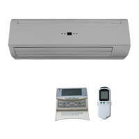
Overview of unit design, efficiency, quiet operation, and appearance.
Details specifications for HWN-EC series, including performance data.
Provides 3-speed specifications for HWN-EC series models.
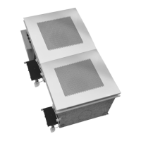
Technical drawings showing dimensions for specific HWN-EC models.
Instructions for installing the high-wall unit.
Guidance on choosing the optimal installation location for the unit.
Specifies the dimensions and requirements for the unit's mounting plate.
Step-by-step guide for securely mounting the unit's plate on the wall.
Instructions for correctly drilling the hole for condensate drainage.
Steps for mounting and securing the indoor hydronic unit onto the plate.
Guidelines for installing the condensate drain piping correctly.
Procedures for unit maintenance and initial preparations.
How to open and close the unit's lift-up grille cover.
Detailed steps for removing the front cover assembly of the unit.
Procedure for purging air from the unit's water coil and system.
Information on how unit components are wired to the terminal block.
Guidance on connecting pipes to the unit's valves.
Details on the EBWPCGH-EC controller for FCU units.
Defines abbreviations used for control parameters and signals.
Lists and defines the inputs and outputs for the FCU controller.
Provides the wiring diagram for the EBWPCGH-EC controller.
Details DIP switch settings for configuring the unit's operation.
Explains the control logic for 2-pipe systems, including modes and protections.
Control logic specific to 2-pipe systems with thermoelectric valves.
Control logic for 2-pipe systems without thermoelectric valves.
Explains the control logic for 4-pipe systems.
Details how the auto fan speed function operates in different modes.
Instructions for controlling the louver position via handset or wall pad.
Describes the buzzer response to commands from master/slave units.
Explains the auto-restart function using non-volatile memory.
Guide to operating the control panel on the high-wall unit.
Overview of the unit's LED indicators and their functions.
Explains LED indications for various error conditions and remedies.
Describes LED indications for master unit defect status of slave units.
Introduction to the master-slave networking system.
Explains the master-slave network configuration.
Step-by-step guide for setting up the master-slave network.
Details the communication methods between master and slave units.
Illustrates the wiring diagram for a master-slave network connection.
Details the SK-NCSWC-002 limited function FCU controller.
Lists and defines inputs and outputs for the limited function controller.
Provides the wiring diagram for the SK-NCSWC-002 controller.
Details DIP switch configurations for the limited function controller.
Specifies the control logic for the limited function FCU controller.
Describes the LED indicators for the limited function controller.
Lists error descriptions and remedies for the limited function controller.
Overview of the remote control handset functions and buttons.
Introduction to the wired wall pad interface.
Explains the layout and elements of the wired wall pad display.
Instructions on how to operate the wired wall pad.
| Power Supply | 220-240V, 50Hz |
|---|---|
| Refrigerant | R410A |
| Type | Wall Mounted |
| Noise Level (Outdoor Unit) | 50 dB |
| Outdoor Unit Weight | 30 kg |