Do you have a question about the AESYS Standard Sign System and is the answer not in the manual?
Outlines the manual's scope, target audience, and content coverage.
States limitations on the manual's accuracy and warranty.
Details safety standards and PPE requirements for working with equipment.
Provides details on manual revisions, dates, and approval.
Explains safety symbols used in the manual and on equipment.
Defines hazard levels and terms like DANGER, WARNING, CAUTION.
Covers crucial safety precautions for maintenance and service procedures.
Offers recommendations for routine maintenance and installation of signs and CCUs.
Explains how to identify the manual's version and publication number.
Discusses how future system changes and firmware updates will be handled.
Defines abbreviations and technical terms used throughout the manual.
Introduces the LED Standard Sign System, its performance, and components.
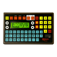
Introduces the KC640 Central Control Unit (CCU) as the on-board controller.
Details the major controls and functions of the KC640 CCU.
Describes the CCU's boot-up sequence and self-test process.
Provides instructions for installing a SmartMedia card into the CCU.
Explains how to select and send destination or message data to the signs.
Explains the meaning of "Status 2" errors and their causes.
Offers steps to diagnose and resolve "Status 2" communication errors.
Describes the CCU's LCD display for code numbers and destination messages.
Details how to enter dash sign information for display.
Explains the procedure for selecting and displaying P/R messages on the CCU.
Outlines the steps to delete public relation messages from the CCU.
Describes the warning message for invalid code numbers entered into the CCU.
Explains how to program and select alternate destinations A and B.
Describes how to use function keys to navigate through destination lists.
Details the process for turning off or blanking the signs using the CCU.
Explains how to enter the CCU's second level mode for configuration.
Guides on adjusting the sign's display brightness via the CCU.
Describes how to enable or disable the internal sign display using the CCU.
Explains how to set the display duration for Public Relations messages.
Covers the Line + Terminus mode for advanced message entry.
Details disabling displays to save battery power when the vehicle is off.
Explains enabling or disabling the dash sign display.
Describes setting the data input protocol to decimal or hexadecimal.
Details how to modify or manage access code passwords for the CCU.
Provides steps to reset the CCU to its default factory settings.
Explains how to reset or disable alarms on the CCU.
Describes an error message related to the emergency button connector or circuit.
Explains the functionality of the emergency/panic alarm system.
Introduces the feature for entering custom text messages via the keypad.
Guides on the step-by-step process for entering manual input messages.
Details specific key functions for editing manual input messages.
Provides supplemental technical information for the CCU.
Explains how the CCU reverts to the current destination if no input is received.
Advises on acquiring access codes and password recovery procedures.
Describes methods for loading destination and message data into the CCU.
Details the process of updating the CCU's firmware using a SmartMedia card.
Provides additional information on CCU composition and component operation.
Discusses programs like BOOT, FIRMWARE, and TRX files for the CCU.
Presents information regarding the hardware components of the KC640 CCU.
Lists the main technical specifications of the KC640 CCU.
Introduces the display panels (signs) and their role in the system.
Describes the main electronic components found within the signs.
Details the CPU circuit board and its key features and components.
Explains the role of the microprocessor as the active component of the CPU board.
Describes EPROM memory and its function in storing data and programs.
Explains the function of DIP switches for setting sign addresses.
Details the PLD's role in performing auxiliary functions within the sign.
Describes the dedicated power supply on the CPU board for improved isolation.
Explains how CPU boards interface with the CCU using specific standards.
Describes the function of filters in removing unwanted signal components.
Details the power supply circuit board's role in generating low voltage levels.
Explains the transient suppressor's function in protecting sign components from spikes.
Describes the function of color management boards in rainbow-type signs.
Details the LED circuit boards responsible for displaying information.
Provides instructions and safety warnings for accessing sign components for servicing.
Subdivides software into CCU and display sign categories.
Lists software components like BOOT, FIRMWARE, and TRX files for the CCU.
Describes FIRMWARE, FONT, and PLD software for sign operation.
Introduces troubleshooting methods and essential knowledge for system diagnosis.
Covers diagnosing and resolving hardware anomalies and component failures.
Provides specific troubleshooting steps for KC640 CCU issues like powering up and transmission errors.
Offers solutions for common sign problems such as not powering on or displaying messages.
Explains how to use parts catalogs for identifying and ordering replacement parts.
Introduces illustrations and details for electrical connections and cable harnesses.
Advises on identifying and confirming sign mounting bracket designs.
Mentions that printed circuit boards are identified in respective parts catalogs.
| Brand | AESYS |
|---|---|
| Model | Standard Sign System |
| Category | Automobile Electronics |
| Language | English |