Do you have a question about the Afag SIGA B.7/65.1 V6 and is the answer not in the manual?
Explains the meaning of symbols, notes, and risk levels according to ISO 3864-2 for safe operation.
Provides essential information for correct product application and safety for technically qualified personnel.
Defines the intended use of the units as electrical controllers for industrial plants.
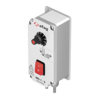
Describes the electronic frequency control device SIGA for continuous control of inductive loads like conveyors.
Lists technical specifications, dimensions, and protection degrees of the SIGA controller.
Instructions for mounting the controller, including screw locations and drive cable shielding.
Details connection diagrams for power supply, load, and control inputs.
Guide on determining mechanical resonant frequency and adjusting output frequency for optimal performance.
Steps for commissioning the control device, including data comparison and connections.
Explains the documentation's conventions for keyboard and input logic levels (LO/HI).
Details the front panel keyboard layout, display segments, and button functions.
Describes initial system messages and display indicators after power-on.
Explains the display segments and their corresponding operational behavior.
Lists and describes different parameter levels (0, 6, b) and their accessible parameters.
Details parameters for Amplitude (A), Swingfrequency (F), soft-start/stop (SA/SS), and setpoint (AE).
Describes parameter F1 for logic gates and input signal processing.
Details parameters F1, S1, and S2 related to logic elements and timing delays.
Explains parameter L for logical operation of inputs and LE6/LEb for signal inclusion.
Provides truth tables for AND, OR, and PACK-Up logic combinations with input signals.
Explains status display codes for feeder operation based on sensor input and logic levels.
Table detailing parameters, their values, and factory settings for instrument configuration.
Procedure for setting the output amplitude of the vibratory drive.
Procedure for adjusting the swing frequency of the vibratory drive.
Procedure for setting the desired setpoint for the vibratory drive's operation.
Procedure for inverting the control signal for input E6, affecting logic processing.
General guidance on programming other parameters like approaching, activating CODE, changing, and saving.
Step-by-step procedure for safely replacing a defective fuse in the control unit.
Table listing common disorders, their causes, and recommended repairing actions.
| Brand | Afag |
|---|---|
| Model | SIGA B.7/65.1 V6 |
| Category | Controller |
| Language | English |