1.
Ensure the AG Dispenser is placed on the ground in a stable condition.
2. If the
AG Dispenser is fitted with a 3
tractor and attach the lower link arms of the tractor to the lower attachment points of the 3 point
frame, using the hitch pins supplied, and secure with lynch pins.
3.
Attach the tractor top link to t
4.
Adjust the tractor link arms stabilisers so that the AG Dispenser is held central and there is no
undue lateral movement.
5. If the AG
Dispenser is fitted with the spool valve kit then ensure that th
cannot interfere with the tractor in any way.
6. If using A-
frame attachment, ensure the female and male frame are compatible.
7.
Lower link arms may need to be adjusted into the lowest position.
8. Ensure A-
frame is vertical at all times.
9. Once
attached, ensure the latch is securely located in the female A
10.
Finally, ensure all the guards are fitted correctly before use.
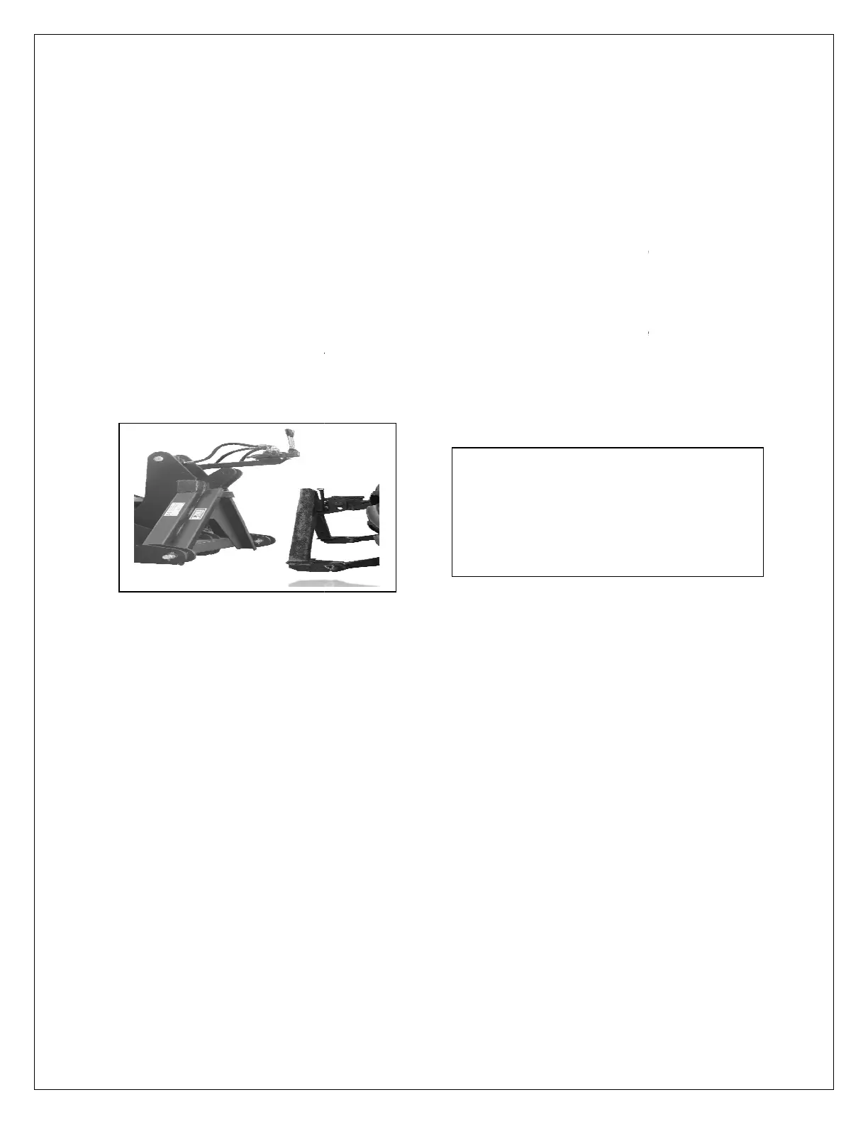
Fig 2. Connection method for A
7
-
Ensure the AG Dispenser is placed on the ground in a stable condition.
AG Dispenser is fitted with a 3
point linkage frame, remove the hitch pins, back up the
tractor and attach the lower link arms of the tractor to the lower attachment points of the 3 point
frame, using the hitch pins supplied, and secure with lynch pins.
Attach the tractor top link to t
he 3 point frame and secure, using the pin and lynch pin.
Adjust the tractor link arms stabilisers so that the AG Dispenser is held central and there is no
Dispenser is fitted with the spool valve kit then ensure that th
e valve block and leavers
cannot interfere with the tractor in any way.
frame attachment, ensure the female and male frame are compatible.
Lower link arms may need to be adjusted into the lowest position.
frame is vertical at all times.
attached, ensure the latch is securely located in the female A
-frame.
Finally, ensure all the guards are fitted correctly before use.
The AG tilting mechanism can be
fitted using the 3 point linkage or the
A-frame system.
NB: The male A-
compatible with
the AG tilting mechanism.
frame
point linkage frame, remove the hitch pins, back up the
tractor and attach the lower link arms of the tractor to the lower attachment points of the 3 point
he 3 point frame and secure, using the pin and lynch pin.
Adjust the tractor link arms stabilisers so that the AG Dispenser is held central and there is no
e valve block and leavers
frame attachment, ensure the female and male frame are compatible.
The AG tilting mechanism can be
fitted using the 3 point linkage or the
-frame of
the AG tilting mechanism.
 Loading...