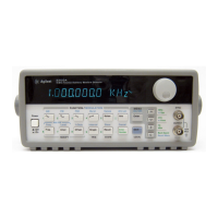
4 Install the Phase-Lock assembly in the Agilent 33120A chassis.
Before installing the Phase-Lock assembly, make sure that the red and
black wires for the instrument fan are clear of the rear-panel holes.
With the Phase-Lock assembly positioned component side down,
insert the two
BNC connectors through the holes previously cut in
the rear-panel label.
5 Secure the Phase-Lock assembly in place.
As shown above, place one lock washer and one hex nut (included with
the retrofit kit) on each of the two
BNC connectors. To prevent cross-
threading, be sure to hand-tighten the hex nuts at least one turn before
using a tool.
3
Lock Washer (2190-0699)
Hex Nut (2940-0256)
Component Side
Down
Top View
Side View

 Loading...