34907A
Multifunction Module
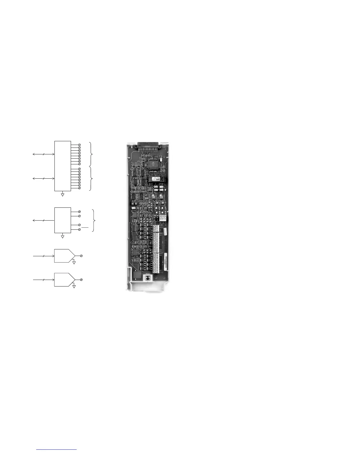
• 16 bits of digital input and output
• 100 kHz totalizer input
• Two ±12V analog outputs
The Agilent 34907A allows great flexibility for a
variety of sense and control applications. It com-
bines two 8-bit ports of digital input and output, a
100 kHz gated totalizer, and two ±12V analog out-
puts—all on a single earth-referenced module. The
digital inputs and totalizer input may be included
in a scan. Alarm limits for the digital and event
counter inputs are evaluated continuously, captur-
ing and logging alarm conditions even between
scans.
Digital Input/Ouput
Use the digital outputs with an external power
supply to control microwave switches and attenua-
tors, solenoids, power relays, indicators, and more.
Use the digital inputs to sense limit switch and dig-
ital bus status. There are no complex handshake
modes; reads and writes are initiated either from
the front panel or the bus.
Digital Input/Output
Port 1, 2 8 bit, input or output, nonisolated
Vin(L) < 0.8V (TTL)
Vin(H) > 2.0V (TTL)
Vout(L) < 0.8V @ Iout = -400 mA
Vout(H) > 2.4V @ Iout = 1 mA
Vin(H) max < 42V with external open drain pull-up
Alarming Maskable pattern match or state change
Speed 4 ms (max) alarm sampling
Latency 5 ms (typical) to 34970A alarm output
Read/Write Speed 95/s
Totalize Input
Count events from devices like photo interrupters,
limit switches, and Hall-effect sensors.
It keeps an updated total which can be read via the
front panel or programmatically at any time. With
26 bits of resolution, it can count events at full
speed for nearly 11 minutes without an overflow.
Totalize Input
Max Count 2
26
- 1
Totalize Input 100 kHz (max) Rising or falling edge,
programmable
Signal level 1 Vp-p (min) 42 Vpk (max)
Threshold 0V or TTL, jumper selectable
Gate Input TTL-Hi, TTL-Lo, or none
Count Reset Manual or Read + Reset
Read Speed 85/s
Analog Output
Use the two electronically calibrated analog out-
puts to source bias voltages to your device under
test, to control your analog programmable power
supplies, or use the outputs as setpoints for your
control systems. The outputs are programmed
directly in volts, either from the front panel or
from the bus.
Analog Output
DAC 1, 2 ± 12V, nonisolated
Resolution 1 mV
I
OUT
10 mA max
Settling time 1 ms to 0.01% of output
Accuracy ±(% of output + mV)
1 year ±5°C 0.25% + 20 mV
Temp. Coefficient ± ( 0.015%
+ 1 mV)/°C
22
 Loading...


