Chapter 2 143
Making Adjustments
23. BITG Power Level for Option 010
Procedure
1. Set the analyzer LINE switch to off. Disconnect the line cord. Remove
the cover assembly, then reconnect the line cord.
2. Set the analyzer AOFST by pressing the following keys.
PRESET
FREQUENCY, −2001, Hz
CAL, More 1 of 4, More 2 of 4, DEFAULT CAL DATA
CAL, More 1 of 4, More 2 of 4
SERV DIAG, DISPLAY CAL DATA, NEXT PAGE
Verify that AOFST=0 under the tracking generator readouts.
3. Connect the cable between the RF OUT 50 Ω and INPUT 50 Ω
connectors on the analyzer.
4. Press
PRESET on the analyzer and set the controls as follows:
CENTER FREQ ........................................... 300MHz
SPAN .................................................................... 0Hz
5. On the analyzer, press the following keys.
BW, 10, kHz
AUX CTRL, TRACK GEN, SRC PWR ON OFF (ON), 10, −dBm
6. On the analyzer, press TRACKING PEAK. Wait for the PEAKING
message to disappear.
7. Zero and calibrate the measuring-receiver/power-sensor combination
in log mode (power levels readout in dBm). Enter the power sensor
300 MHz cal factor into the measuring receiver.
8. Disconnect the cable from the RF OUT 50 Ω connector, then connect
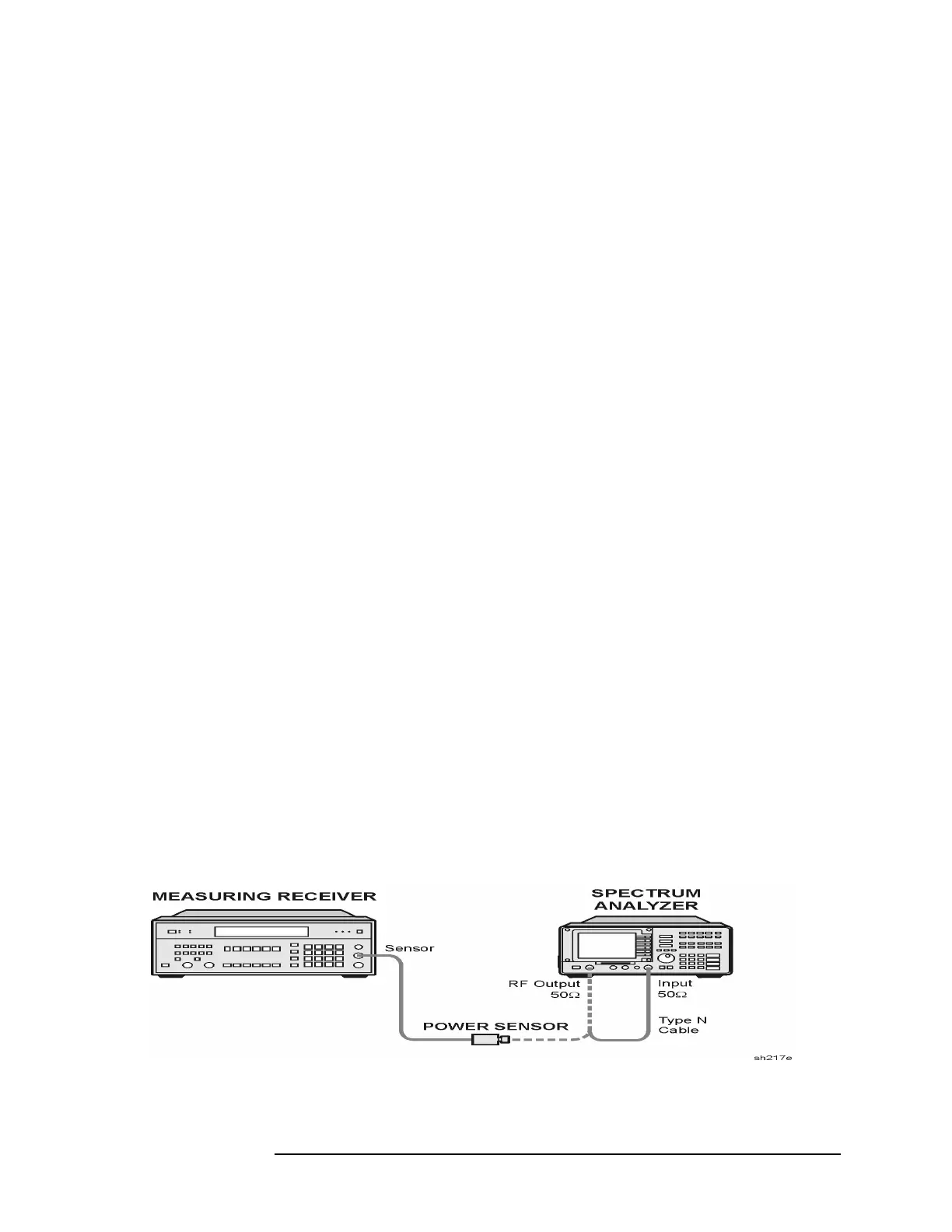
the power sensor to the RF OUT 50 Ω connector. See Figure 2-34.
Figure 2-34 BITG Power Level Adjustment Setup
 Loading...

