90 Chapter2
Making Adjustments
13. Third Converter and Second IF Bandpass
28.Subtract the Mismatch Error (step 22) from the Uncorrected
Insertion Loss (step 22). This is the corrected insertion loss.
Corrected Insertion Loss____________________dB
For example, if the Mismatch Error is +0.3 dB and the uncorrected
Insertion Loss is −10.2 dB, subtracting the mismatch error to the
insertion loss gives a corrected reading of −10.5 dB.
300 MHz Calibrator Amplitude Adjustment
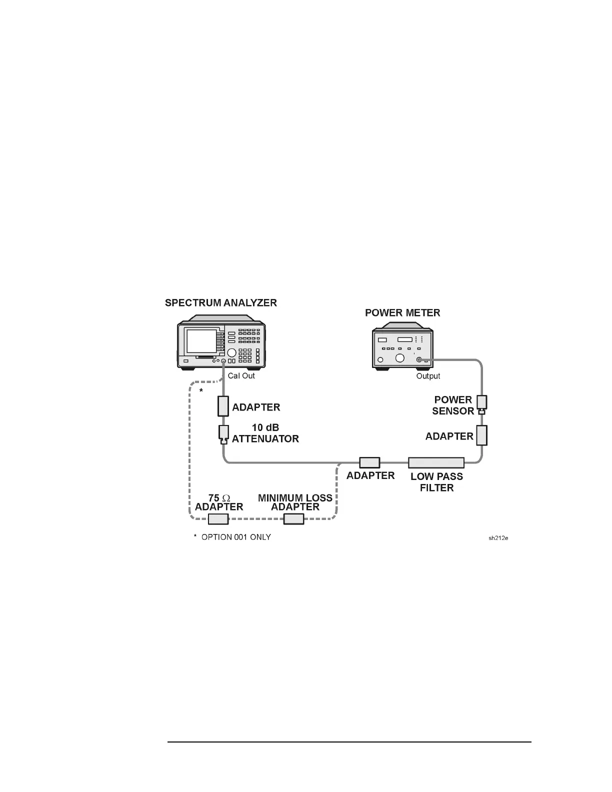
29.Connect the equipment as shown in Figure 2-24. The analyzer
should be positioned so that the setup of the adapters, LPF and
attenuator do not bind. It may be necessary to support the center of
gravity of the devices.
Figure 2-24 300 MHz Calibrator Amplitude Accuracy Test Setup
30.On the power meter, press the dBm mode key. Record the power
meter reading in dBm.
Power Meter Reading____________________dBm
31.Subtract the Corrected Insertion Loss (step 23) from the power
meter reading (step 25) and record as the CAL OUT power. The CAL
OUT should be −20 dBm ±0.4 dB.
CAL OUT Power = Power Meter Reading − Corrected Insert Loss
 Loading...

