Installation Note E4400-90214 17
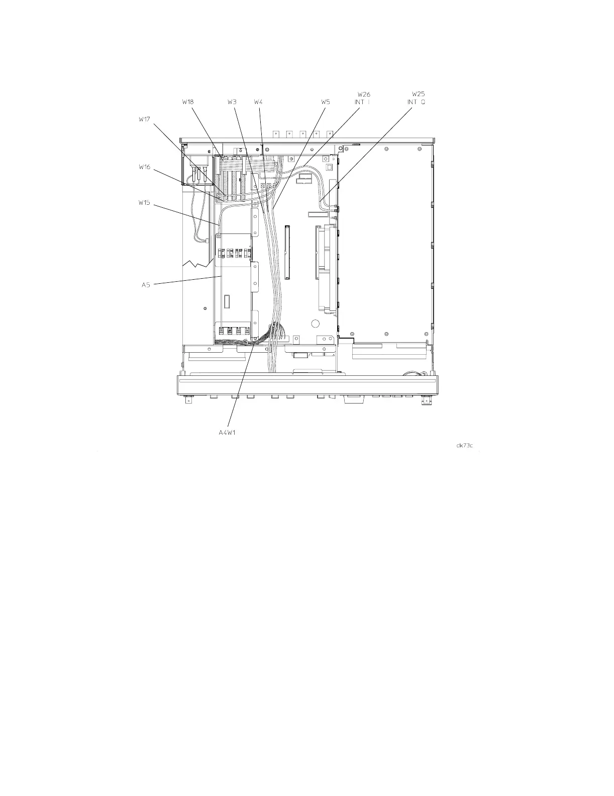
Figure 7 Cable Locations (Option UN3/4 or UN8/9 Not Installed)
Install the Option UND Board Assembly (Options UN3/4 or UN8/9 Installed)
1. Cut out a single Option UND label and attach it to the serial tag option location on the rear panel.
This identifies the signal generator as having Option UND installed.
2. Refer to Figure 8 on page 18 and the Cable Routing table on page 19. Insert the A5 dual arbitrary
waveform generator board into the motherboard connector labeled A14J1.
3. Connect the ribbon cable, W18, from the A17 rear-panel interface board to the A5 dual arbitrary
waveform generator board (if Options UN3/4 are installed) or the A7 real-time I/Q baseband
generator (if Option UN8/9 is installed).
4. Disconnect W17 from A7J1 I OUT on the A7 baseband generator board and connect it to
A5J1 I OUT on the A5 dual arbitrary waveform generator board.
5. Disconnect W16 from A7J2 Q OUT on the A7 baseband generator board and connect it to
A5J2 Q OUT on the A5 dual arbitrary waveform generator board.
6. Disconnect W15 from A7J3 (13 MHz) on the A7 baseband generator board and connect it to
A5J3 on the A5 dual arbitrary waveform generator board.
7. Connect W24 between A5J4 and A7J3 (13 MHz).
8. See Figure 8 and Figure 9 on page 18 to verify cable routings.
 Loading...


