Installation Note E4400-90214 19
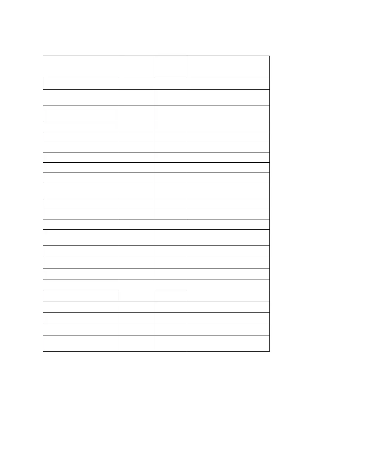
Cable Routing (front to rear)
Cable Description
Reference
Designator
Color
Number
a
a Cable color numbers appear in the CONNECTOR/CABLE DIAGRAM located on the top of
the RF MODULE CAGE on the inside cover of the signal generator.
Connection
Point to Point
Option UN8 Only (Figure 8 on page 18)
RIBBON CABLE
INTERCONNECT
W19
–
A7P300 to A8P3
RIBBON CABLE
INTERCONNECT
W27
–
A7P10 to A8P4
BASEBAND GEN REF IN W15 8 Rear Panel to A7P403
Q OUT W16 9 Rear Panel to A7P404
I OUT W17 09 Rear Panel to A7P405
DATA W3 5 Front Panel to A14P5
SYMBOL SYNC W5 6 Front Panel to A14P7
DATA CLOCK W4 7 Front Panel to A14P6
REAR PANEL INTERFACE
CABLE
W18 – Rear Panel Interface (A17) to A8P2
INT Q W25 05 Daughter Board (A15) to A14P103
INT I W26 06 Daughter Board (A15) to A14P102
Option UN8 & Option UN7 (Figure 8 on page 18)
RIBBON CABLE BERT, REAR
PANEL
A18W1
–
Rear Panel to A6P4
BER GATE IN W21
–
Rear Panel to A6P3
BER CLK IN W22
–
Rear Panel to A6P2
BER DATA IN W23
–
Rear Panel to A6P1
Option UN8/9 (Figure 8 on page 18)
BASEBAND 13 MHz W24
–
A5J4 to A7J3
BASEBAND GEN REF W15
–
Rear Panel to A5J3
Q OUT W16
–
Rear Panel to A5J2
I OUT W17
–
Rear Panel to A5J1
REAR PANEL INTERFACE
CABLE
W18
–
Rear Panel Interface (A17) to A5P1
 Loading...


