Chapter 5 291
Concepts
Analog Modulation Concepts
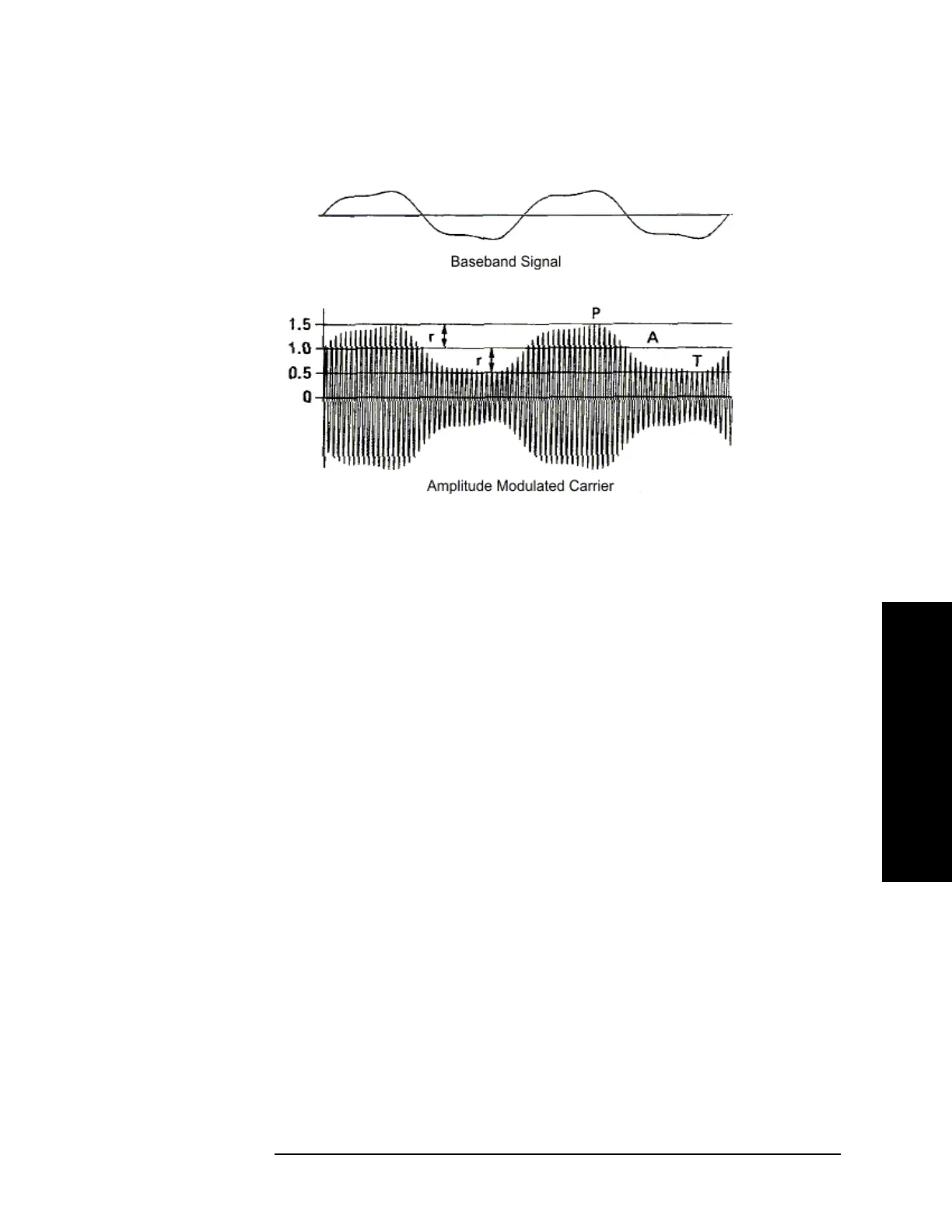
Figure 5-4 Baseband Signal and the Corresponding Amplitude Modulated Carrier
In the example of Figure 5-4 on page 291, P = 1.5 and T = 0.5; therefore,
m = (1.5 - 0.5) / (1.5 + 0.5) * 100% = 50%.
Figure 5-5 on page 292 shows AM signals with modulation indexes varying from
0 to 100%.
When the baseband signal is symmetrical, the modulation index can also be
expressed in terms of the average carrier level, A, and the envelope peak, r, relative
to the carrier. Then P = A + r, and T = A - r, and the expression for modulation
index becomes
m = (A + r − A + r) / (A + r + A − r) * 100% = r / A * 100%.
This is the expression which the Measuring Receiver evaluates when making an
AM measurement. Referring back to Figure 5-4 on page 291, it is apparent that A
= 1 and r = 0.5 so
m = 0.5 / 1 * 100% = 50%
as before.

 Loading...


