374 Chapter 8
N5531S Measuring Receiver Performance Verification
Performance Verification Tests
N5531S Measuring Receiver Performance
Verification
Test Setup
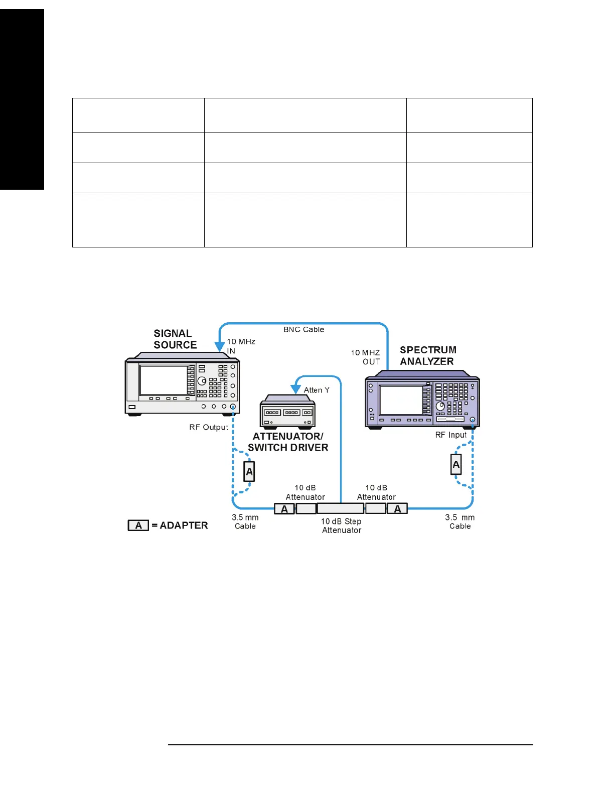
Figure 8-2 Relative TRFL Measurement Test Setup
Test Procedure
1. See Figure 8-2. When connecting equipment, assure proper connector care and
connector torque settings are followed. SMA/ 3.5mm cable connectors are to
receive 8 inch-pounds of torque. All connections must be cleaned with alcohol.
2.
Preset the signal source and the PSA.
3. On the PSA, perform the
Auto Align by pressing System, Alignments, Align All
Now
.
3.5 mm (f) to 2.4 mm (f) For source output or PSA input on high
frequency models
Agilent 11901B
3.5 mm (f) to 3.5 mm (f) For output of 20 GHz source or input to E4440A
opt BAB
1250-1749
Type N (m) to 3.5 mm (f)
2 or 3 required
For connection to fixed attenuators.
Also, if PSA has type N input connector, this
adapter is required
1250-1744
Table 8-6 Test Equipment
Instrument Critical Specifications
(for this test)
Recommended Model
 Loading...


