2
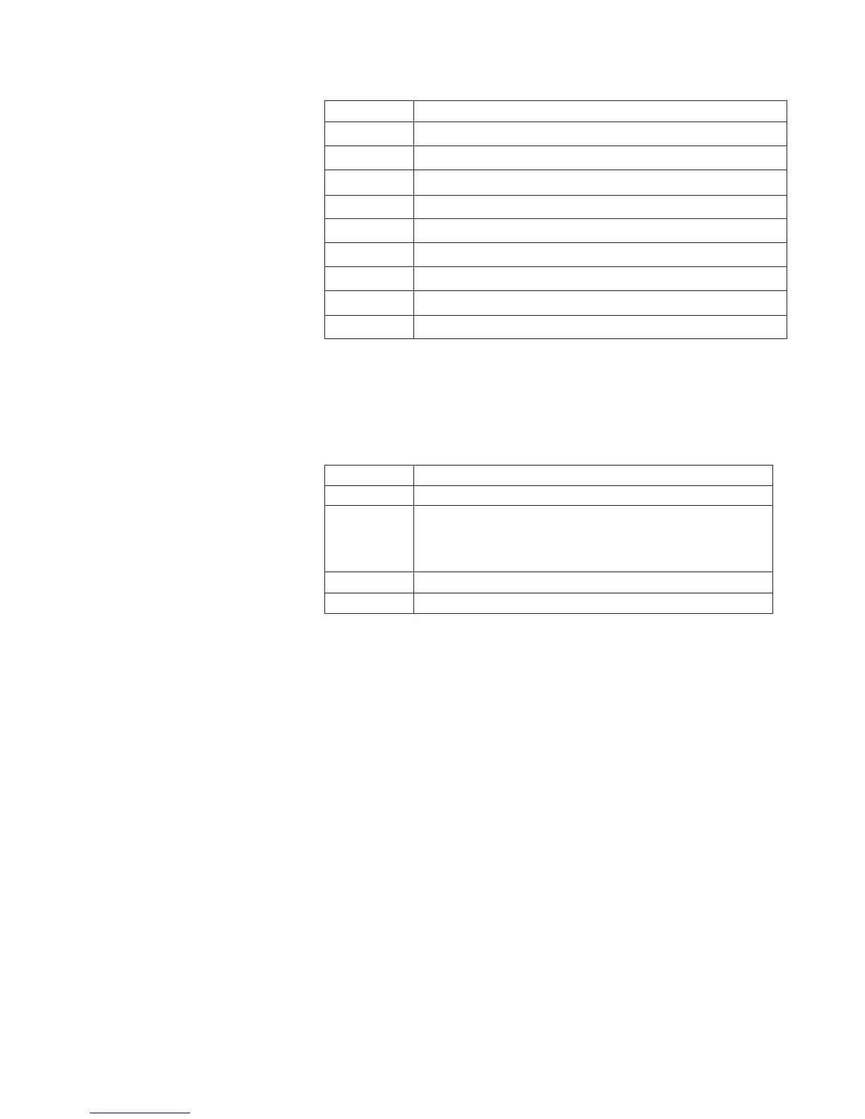
U2000 Series Models
Sensor model Description
U2000A 10 MHz to 18 GHz, –60 dBm to +20 dBm USB Power Sensor, N-type (m)
U2001A 10 MHz to 6 GHz, –60 dBm to +20 dBm USB Power Sensor, N-type (m)
U2002A 50 MHz to 24 GHz, –60 dBm to +20 dBm USB Power Sensor, 3.5 mm (m)
U2004A 9 kHz to 6 GHz, –60 dBm to +20 dBm USB Power Sensor, N-type (m)
U2000H 10 MHz to 18 GHz, –50 dBm to +30 dBm USB Power Sensor, N-type (m)
U2001H 10 MHz to 6 GHz , –50 dBm to +30 dBm USB Power Sensor, N-type (m)
U2002H 50 MHz to 24 GHz, –50 dBm to +30 dBm USB Power Sensor, 3.5 mm (m)
U2000B 10 MHz to 18 GHz, –30 dBm to +44 dBm USB Power Sensor, N-type (m)
U2001B 10 MHz to 6 GHz, –30 dBm to +44 dBm USB Power Sensor, N-type (m)
Options and Accessories
Special Options
Option Number Description
U2001A-H03 U2001A sensor with extended frequency range, 3 MHz to 6 GHz
U2001A-H16 With 1K ohms input trigger impedance. Higher impedance is typically
required when several instruments’ input trigger ports are connected
in parallel for triggering purpose. Standard option has 50 ohms input
trigger impedance.
U2001A-H25 U2001A sensor with extended power range, -60 dBm to +25 dBm
U2002A-H26 U2002A sensor with extended frequency range, 10 MHz to 26.5 GHz
Calibration Documentation
Option U200xx-A6J• : ANSI Z540 compliance calibration test data including
measurement uncertainties
Option U200xx-1A7• : ISO17025 compliance calibration test data including
measurement uncertainties
Documentation
A hard copy and CD version of the English language operating and service guide,
programming guide, and the N1918A Power Analysis Assembly are shipped
together with the USB power sensor as standard items.
Introduction
This confi guration guide describes the
standard confi gurations, options, and
compatible accessories for the U2000
Series USB power sensors. Contact
your local Agilent representative for
more information.