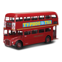
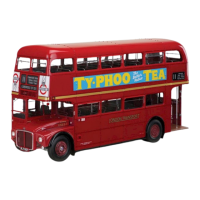
The device described in this manual is a model of the London Transport Routemaster Bus, specifically model RM 857, designed for assembly by Agora Models. This manual covers "Pack 10" of the build, encompassing stages 91 through 100, which focus on fitting various structural components, windows, doors, lighting, and roof panels.
Function Description:
The Routemaster Bus model is a detailed, multi-stage replica of the iconic London double-decker bus. The assembly process involves constructing the bus's lower and upper decks, including their frameworks, windows, doors, and internal mechanisms. The model is designed to be highly realistic, incorporating features such as opening windows, a driver's door, and an LED lighting panel for the bus blinds. The assembly instructions guide the user through fitting these components, ensuring a precise and accurate representation of the original vehicle.
Important Technical Specifications (as inferred from the manual):
- Model Scale: Not explicitly stated, but implied to be a large-scale model given the intricate details and numerous parts.
- Materials: Primarily red plastic for the main body framework and roof panels, clear plastic for windows, and various metal screws for assembly.
- Power Source: Requires batteries for the LED lighting panel (battery box 56B is mentioned, implying battery operation).
- Assembly Stages: This pack covers stages 91-100, indicating a comprehensive multi-stage build.
- Components: Includes a wide array of parts such as:
- Left and right wall frameworks for both lower and upper decks.
- Window panes, frames, bars, and winders (sliding and non-opening types).
- Driver's door components (outer/inner panels, handle, window pane).
- LED light panel for bus blinds (part 71E).
- Ceiling assemblies for the upper deck.
- Roof panels and finishing strips.
- Rain shields for windows.
- Various screws (BP, OP, JP, NM, EM, MM, GM, AP, FM, KM) of different sizes (e.g., 1.5 x 3mm, 1.7 x 5mm, 2.3 x 4mm).
- Wiring and circuit board (57E) for electrical components.
- Handrails and grab poles.
- Number plate and brake light.
Usage Features:
- Detailed Assembly: The manual provides step-by-step instructions with clear diagrams for each stage, making the complex build manageable.
- Realistic Functionality: Features like sliding windows (e.g., 91F, 92E, 94G, 95E) and an opening driver's door (stage 93) add to the model's realism and interactive appeal.
- Electrical Components: The inclusion of an LED light panel (71E) and a brake light (96C) with associated wiring (72A, 72B, 72C) and a circuit board (57E) allows for illuminated features, enhancing the display value.
- Modular Construction: The bus is built in sections (e.g., lower deck framework, upper deck assembly, roof panels), which are then integrated, simplifying the construction process.
- Expert Advice: The manual includes "Expert Advice" sections, such as the one for the "Bell Pull Mechanism," offering solutions to potential assembly challenges and improving the model's functionality.
Maintenance Features (as inferred from the manual):
- Careful Handling: Users are advised to "Handle with care" during assembly, especially when dealing with larger sub-assemblies like the upper and lower deck, to prevent parts from slipping or becoming damaged.
- Storage Recommendations: An important note advises to "Store your model away from direct sunlight, to avoid damage to the windows," indicating that the plastic window components may be susceptible to heat or UV degradation.
- Screw Management: The manual recommends identifying and keeping screws "to hand in separate containers for easy handling," which is a practical tip for managing the numerous small parts during assembly.
- Wiring Organization: Instructions are provided for "Organising the wiring" neatly around the circuit board, which is crucial for the proper functioning of the electrical components and for maintaining the model's aesthetic.
- Component Testing: Before fitting the light panel, users are instructed to "test that the light is working. Re-test once it has been fitted," ensuring that electrical components are functional before final assembly.
- Adjustments and Troubleshooting: The "Expert Advice" section on the "Bell Pull Mechanism" provides troubleshooting steps (re-tying cord, filing a notch) to ensure proper operation, highlighting that minor adjustments may be necessary during the build.
- Partial Screw Tightening: When fitting large frames with numerous screws, it is advised to "only partially fit the screws at first and then fully tighten once they are all in place," which helps ensure proper alignment and prevents stress on the parts.
- Temporary Securing: The use of "low-tack tape" is suggested for temporarily securing components like the LED panel, allowing for adjustments before final fixation.
- Tweezers for Small Parts: The manual suggests using "long tweezers" to maneuver small parts like handrails into place, indicating the need for precision tools during assembly.