03. METAL DETAILS FOR THE FORWARD SUPERSTRUCTURE
03 04
05 06
01 02
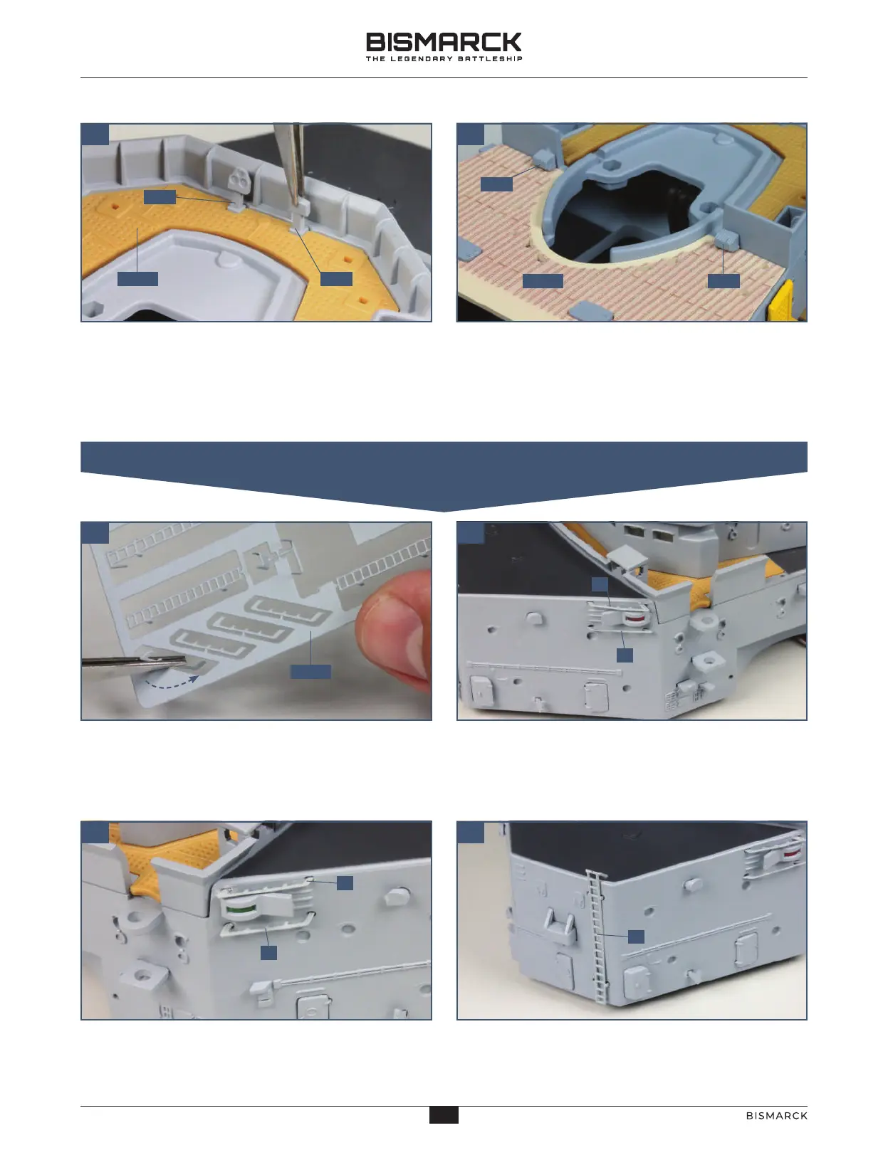
Cut the control station I2 and the engine
communication console I3 from the frame and identify
the fixing points on the deck 29-02 at the front of the
superstructure. Ensure they are fitted the right way
round, as shown, and fix in place with a little superglue.
Cut the two ventilators I4 from the frame and
identify the fixing points on either side of the opening
on deck 29-04. Fix in place with a little superglue.
Take the metal frame 32-07 and remove all the parts:
you can grip them with tweezers and twist them or
use a side cutter to clip them from the frame. Use a
fine file to remove any rough edges.
The first two metal parts are fitted above and below
the port navigation light. Note the angle of the fixing
bars at each end – the sharper angle goes at the rear.
The next two metal parts are fitted above and below
the starboard navigation light. Again, make sure you
have the parts the right way round.
Take the longer ladder 2 and fit it to the front
of the superstructure, fixing it in place with
a little superglue.
29-02 I2
29-04 I4
32-07
1
I3
I4
1
1
1
2
41
41
AGORAMODELS BISMARCK
PB
AGORAMODELS BISMARCK
 Loading...