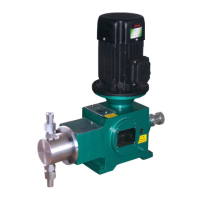
The Ailipu J-X Series Plunger Metering Pump is a positive displacement pump designed for precise liquid dosing in various industrial applications. Manufactured by Zhejiang Ailipu Technology Co., Ltd., these pumps adhere to GB7782-2008 Metering Pump and API std 675-2014 Positive Displacement Pumps-Controlled Volume standards, ensuring reliability and accuracy.
Function Description:
The metering pump operates by converting the rotational motion of a motor into a reciprocating linear motion of a plunger. This is achieved through a driving end mechanism comprising an arch cam, a stroke adjustment mechanism, and a worm gear reduction system. The plunger's reciprocating action creates a suction stroke, drawing liquid into the pump head cavity, and a discharge stroke, pushing the liquid into the discharge line. Check valves at the inlet and outlet ensure unidirectional flow and prevent backflow. The pump's design allows for precise control over the flow rate, making it suitable for applications requiring accurate dosing.
Important Technical Specifications:
- Flow Regulation Modes:
- Stroke Adjustment: The plunger's stroke length can be adjusted (optimal stroke: 30-100%) during shutdown or operation, achieving a measurement accuracy within ±1%. This adjustment is performed manually via a handwheel and indicated by a stroke scale and micrometer, or automatically through remote control and computer-based flow control.
- Pump Speed Regulation: Flow can also be regulated by changing the motor's power frequency via frequency conversion, enabling remote control and computer-based management.
- Liquid Handling Capabilities:
- Temperature Range: -30°C to 250°C (regular plunger pumps: -30°C to 200°C).
- Viscosity Range: 0.3 to 2,000 mm²/s (regular plunger pumps: 0.3 to 800 mm²/s). For viscosities exceeding these ranges, consultation with AILIPU company is advised.
- Solid Particle Size: Not more than 0.1 mm.
- Working Pressure: Wide range, with a maximum pressure of up to 80 MPa.
- Transmission Box Oil Capacity: 0.9L.
- Motor Temperature: Maximum allowable temperature of 70°C.
- Lubricating Oil Temperature: Maximum allowable temperature of 65°C.
- Materials: The pump head and valve materials can be selected from various options including 304, 316L, Hastelloy C, 20# Alloy, Titanium Alloy, PVC, PTFE, PVDF, Carbon Steel, and SS coated with Fluorination, depending on the application and liquid compatibility.
- Connection Methods: Hose, Flange, NPT Thread, Metric Thread, Tapered Thread, Guard Staple.
- Flow Control: Manual, Stroke, Digital.
- Motor Types: Explosion Proof, Variable Frequency, Explosion Proof Variable Frequency, Standard.
- Pump Head Types: Electric Heating, Simple Heat Preservation, Heat Preservation Jacket, High Viscosity.
Usage Features:
- Versatile Applications: Widely used in chemical, petrochemical, metallurgy, electric power, medicine, food, plastic foam, mining machinery, and other fields.
- Simple Structure: Contributes to ease of maintenance.
- Cost-Effectiveness: Offers a good balance of performance and cost.
- High Viscosity Medium Transport: Capable of handling high-viscosity liquids.
- Flow Calibration: Essential for ensuring measurement accuracy, especially in new installations or when operating conditions change. Calibration should be performed at various stroke settings (e.g., 100%, 75%, 50%, 30%, 10%).
- Installation Requirements:
- Must be installed on a dedicated concrete foundation or cast iron platform, fixed with foundation bolts.
- The foundation should be 50-100mm above ground to prevent water damage.
- Adequate space around the pump is required for maintenance and adjustment.
- Suction and discharge pipe diameters should not be less than the pump's inlet/outlet pipe diameters.
- The suction pipe should be as short as possible; for long suction pipes or high-viscosity mediums, the inlet pipe diameter should be increased.
- Measuring instruments (e.g., pressure gauges) should be installed in the connecting pipes.
- Filter devices are required at the end of the suction pipe.
- A safety valve or safety-relief valve (user-provided) must be fitted on the discharge pipe to prevent overpressure.
- A pressure stabilizer (buffer) can be installed near the discharge pipe to reduce pressure fluctuations.
- Outdoor installations require a rain cover.
- A counterbalance valve should be installed at the outlet pipe if the outlet pressure is less than 0.3MPaG or if the inlet pressure is greater than the outlet pressure (artesian phenomenon) to ensure dosing accuracy.
- Operation Procedure:
- Before starting, check all bolts and nuts for tightness.
- Clean anti-corrosive grease or dirt from new pumps using kerosene (avoid scraping).
- Fill the transmission box with L-CKC-N150 (or N220) medium-load industrial gear oil to the midline of the oil leveler.
- Manually turn the motor blade to ensure the plunger moves through its full stroke without jamming.
- Start the motor and verify consistent rotation direction with the pump.
- Ensure inlet and outlet valves on pipes are fully open.
- Monitor for stable operation and absence of abnormal noise; shut down and inspect if noise occurs.
- To shut down, fully open the outlet valve to reduce discharge pressure, then cut off power.
Maintenance Features:
- Regular Oil Level Check: Periodically observe the oil level in the transmission box to prevent it from being too high or low.
- Lubricating Oil Quality: Keep lubricating oil clean and free of impurities.
- Oil Replacement Schedule:
- First month: Once.
- After 6 months: Once every 6 months.
- Internal Inspection: After 5,000-8,000 hours of operation, disassemble the pump to inspect internal parts, and replace vulnerable parts while adjusting fit clearances.
- Long-Term Storage: If the pump is out of service for an extended period, empty media from the hydraulic cylinder, clean the surface, apply anti-rust oil to exposed machining surfaces, and store in a dry, covered location.
- Safety During Maintenance:
- Stop the pump and release system pressure.
- Close pump inlet and outlet valves.
- Post "under maintenance" notices on the power switch.
- Immediately disconnect power during operation if any fault occurs.
- Disassembly and Reassembly:
- Hydraulic End: Involves removing pipe connections, inlet/outlet valve components (flange, sleeve, ball, seat), loosening the plunger locking cap, pulling out the pump head body, and removing the plunger and packing components.
- Driving End: Involves emptying lubricating oil, removing the motor and motor bracket, top bearing seat, worm, outer cover, eccentric gear assembly, adjusting handwheel, adjusting rod, and adjusting rod seat.
- Reassembly: Follows the reverse sequence of disassembly.
- Worm Gear/Worm Meshing: When installing new components, re-measure and re-adjust the meshing center position. Apply red lead to worm gear teeth, rotate manually, and adjust sealing paper pad thickness on the bottom bearing seat to achieve correct meshing.
- Worm Gear Rotation: To prolong service life, the worm gear can be rotated 180 degrees around its axis during inspection and reinstalled if wear is uneven.
- Cross Head and Oil Seal: Ensure no scratches or damage on the cross head surface during installation to maintain sealing effectiveness.
- Motor Fan and Stroke Adjustment: After reassembly, check that the motor fan rotates freely. Adjust the handwheel outward, set the pump stroke to 0, and then adjust the scale on the dial to 0 before locking the handwheel fixed screw.
- Inlet/Outlet Valve Sealing: Crucial for flow accuracy. Perform kerosene leakage tests; if no leakage in 3 minutes, the sealing is good. Otherwise, replace valve balls and seats.
- One-Way Valve Replacement/Cleaning: Remove flange, sleeve, ball, and seat for inspection/replacement. Ensure no pits or damage on valve ball surface or seat orifice. Reinstall all parts correctly, ensuring the one-way valve functions as a check valve. Incorrect installation sequence will prevent liquid discharge.
Fault-finding and Troubleshooting:
A comprehensive checklist is provided for common issues, including:
- Motor not starting: Check power supply, fuse, contactor contacts, reset overload, replace motor.
- No/insufficient liquid discharge: Check suction pipe/filter, open valve, check seal leakage, increase suction pipe diameter, reduce sharp turns, check valve airtightness, replace valve ball/seat, replace seal packing/plunger, stabilize power supply, adjust suction level.
- Pump pressure not meeting parameters: Replace valve, replace seal packing/plunger.
- Low measurement accuracy: Refer to treatment methods, readjust plunger zero point, reduce liquid temperature or increase suction pressure, add back pressure valve on outlet.
- Hot parts/high oil temperature: Replace/fill oil, check lubrication supply, adjust sliding clearance.
- Impact sound during operation: Adjust/replace parts, adjust/reduce valve ball lift height, empty air from medium or increase suction pipe diameter, check worm gear/worm fit clearance, check/clean safety valve and adjust opening pressure.
- Flow regulation mechanism not working: Repair/replace adjusting screw/nut, disassemble and check movement of connecting rod, eccentric gear, crosshead, and crosshead sleeve.
For after-sales service, customers are advised to contact the provided hotline with the pump's unique factory number for model and technical parameter verification.