6
DROPOUT VOLTAGE
The load will cease to conduct if the applied voltage falls below the Dropout Voltage setting;
active in all modes except Constant Voltage. The Dropout Voltage setting is also the threshold for
the Slow Start facility and acts as an offset voltage in Constant Resistance mode.
Slow Start
If Slow Start is enabled, the load will not conduct any current until the source voltage reaches the
Dropout Voltage setting; it will then ramp the controlled variable up (in CC, CP and CG modes) or
down (in CR and CV modes) to the Level setting at a rate determined by the Slew Rate setting.
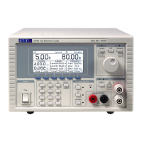
METER SPECIFICATIONS
256 x112 pixel graphic LCD with white LED backlight.
Measured Values
Measured values of current through and voltage across the load.
Power and equivalent load resistance, calculated from Volts and Amps.
CURRENT MONITOR OUTPUT
4mm safety sockets on front panel or terminal block on rear panel.
Ω
Ω
.
50mV per Amp (4 Volts full scale).
± 3Vdc max. to load negative. A connection is required, see
.
REMOTE CONTROL
Digital Remote Interfaces
The LD400P model provides LAN, USB, GPIB and RS232 interfaces for full remote control.
LAN:
Ethernet 100/10base-T connection with auto cross-over detection.
1.4 LXI Core 2011 compliant.
Standard USB 2.0 connection. Operates as virtual COM port.
GPIB: Conforming to IEEE488.1 and IEEE488.2.
Capabilities: SH1, AH1, T6, L4, SR1, RL2, PP1, DC1, DT0, C0, E2.
Standard 9-pin D connection. Baud rate: 9600.
External Control Input Characteristics
Terminal block on rear panel.
400kΩ each input to load negative.
External Analogue Voltage Control
The applied voltage sets the operating level within the selected range.
± 2% ± accuracy of selected range.
External Logic Level (TTL) Control
The applied signal selects between Level A and Level B settings.
+ 1·5V nominal. A logic high selects Level B.