Do you have a question about the Aim ANET1553 Series and is the answer not in the manual?
Overview of ANET1553 module, features, and architecture.
Lists referenced documents, including industry and product-specific standards.
Details the procedure for installing the Board Support Package (BSP).
Covers physical setup, including power and connectors.
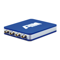
Describes front and back panel connectors for interfaces.
Explains module powering and status LED indications.
Details how to power the module and its startup behavior.
Outlines system requirements for configuring the ANET1553.
Describes connecting ANET1553 modules to a network.
Explains device discovery using the AIM Network Detection Tool.
Covers initial configuration via web browser.
Details static/dynamic IP configuration and network settings.
Explains Wi-Fi device setup for wireless connectivity.
Covers the procedure for updating the module's firmware.
Explains emergency mode for recovery and updates.
Guides on connecting applications to the ANET1553 module.
Guides on connecting to PBA.pro application.
Details connecting via the AIM API-Library.
Explains connection methods to a MIL-STD-1553 bus.
Describes the direct coupling method.
Explains transformer coupling method.
Details functions and features in the System FPGA.
Covers physical interface and coupling modes.
Explains the eight user-programmable Discrete-I/O signals.
Describes the Time Code Processor (TCP) functions.
Steps to open the sample solution in Visual Studio.
Instructions for setting up include directories.
Steps to add preprocessor definitions.
Instructions for adding necessary libraries.
Steps to set the library search path.
Guide on building and executing the sample program.
Details the "Simulator Only" functionality for simulation purposes.
Explains the "Single Function" mode for non-concurrent use of features.
Lists and defines acronyms used throughout the manual.
Describes the panel layout and pinout of the ANET Table Adapter.
Details the ANET1553 rugged housing variant.
Describes the hardware installation for the rugged module.
Lists and describes connectors on the rugged variant.
Details the LEMO connector for power and control.
Explains the DSUB9 connector for MIL-STD-1553.
Details powering the rugged module and its startup.
Lists technical specifications for the rugged variant.
| Brand | Aim |
|---|---|
| Model | ANET1553 Series |
| Category | Network Hardware |
| Language | English |