1
Use a flathead screwdriver to pry
open the panel without scraping it.
Main unit
Included wood
screws x2
Incoming line ports
Please insert the lines from the bottom.
*Make knockouts as necessary.
Mounting height
(device center)
IX-DA: 1,500 mm (5')
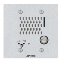
IX-BA: 1,300 mm (4'3")
83.5 mm (3-5/16")
Back wiring Surface wiring
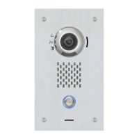
Imaging Range and Mounting Location (IX-DA only)
Imaging Position Settings
The camera angle can be adjusted up or down (-8°, 0°, +15°) using the camera angle adjustment lever.
Set it to the optimal level.
Camera angle adjustment lever
+15°
0°
-8°
(Back)
Wall Mounting
The indicated range is a guideline that may change depending on the installation environment.
Unit
center
Unit
center
Unit
center
Approx. 1,850 mm (6'1")
Approx. 650 mm (2'2")
500
mm
(20")
500
mm
(20")
500
mm
(20")
Approx. 1,200 mm (3'11")
1,500 mm (5')
Approx. 1,850 mm (6'1")
Approx. 700 mm (2'3")
Approx. 1,150 mm (3'9")
1,300 mm (4'3")
Approx. 1,900 mm (6'3")
Approx. 700 mm (2'3")
150 mm (5")
Approx. 1,200 mm (3'11")
1,500 mm (5')
Camera angle 0° Camera angle +15°
If lower due to a level difference
Horizontal
Vertical
Camera angle -8°
Approx. 950 mm (3'1")
500mm (20")
When light enters the camera, the monitor screen may fl icker brightly or the subject may become dark. Try to prevent strong lighting from entering the
camera directly.
Connection Precautions
Cable
The cable is not included with the product.
CAT5e/6 cable
• Use a straight cable when connecting between equipment.
• Do not use a CAT5e/6 cable with a bending angle of less than a
25 mm (1”) radius. A radius of less than 25 mm (1”) could cause a
communication failure.
CAT5e/6 cableCAT5e/6 cable
Radius ≥ 25 mm (1")
Radius < 25 mm (1")
• Do not peel the jacket off the CAT5e/6 cable any more than is
necessary.
• Attach the RJ45 modular plugs using either EIA/TIA-568A or 568B.
Pair4
Pair3
Pair2
Pair1
T568A
Pair4
Pair2
Pair3
Pair1
T568B
12 3 45 6 7812 3 45 6 78
• Use the LAN tester to confi rm conduction before connecting the
CAT5e/6 cable.
• The RJ45 connector with cover cannot be connected to CAT5e/6 cable
terminals for Master Station or Door Stations. Use cables without covers
on the connectors.
• Do not pull the CAT5e/6 cable or apply excessive load.
Cable precautions
• Do not use separate conductors or twisted pair cables.
• Do not use an odd number cable.
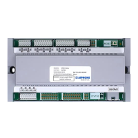
Wiring Connection
Insulate and secure unused wires.
*
1
Contact Input Specifi cations
Input method
Form C dry contact (N/O or N/C)
Level detection method
Fixed detection time
200 msec or more
Contact resistance
Maximum closure resistance: 700 Ω or less
Minimum open resistance: 3 kΩ or more
Terminal short-circuit
current
10 mA or less
Voltage between
the terminals
DC 5V or less (between open terminals)
*
2
Audio Output Specifi cations
Output impedance 600 Ω
Output audio level 300 mVrms (600 Ω when terminated)
*
3
Relay Output Specifi cations
Output method
Form C dry contact (N/O or N/C)
Voltage between
the terminals
AC 24V, 0.5A (resistive load)
DC 24V, 0.5A (resistive load)
Minimum load (AC/DC): 100 mV, 0.1 mA
How to InstallHow to Install How to ConnectHow to Connect
There is no space to accommodate the wiring in the back of the
unit. If you do not use a 1-gang box, please provide openings or
handle exposed wiring in other ways.
 Loading...