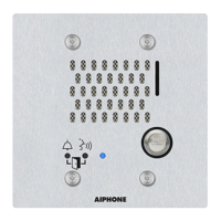
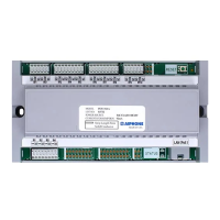
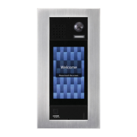
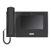
<Wall mounting>
Camera angle -20°
Horizontal
500mm
(1' 7'')
350mm (1' 2'')
1400mm (4' 7'')
Center
of device
1,500mm
(4' 11'')
Camera
position
1575.5mm
(5' 2'')
Vertical
Camera angle 0°
1750mm (5' 9'')
Center
of device
1,500mm
(4' 11'')
Camera
position
1575.5mm
(5' 2'')
500mm
(1' 7'')
350mm (1' 2'')
1200mm (3' 11'')
1550mm (5' 1'')
(1' 7'')
460mm (1' 6'')
When light enters the camera, the monitor screen may flicker brightly or the subject may become dark. Try to prevent strong lighting from entering the
camera directly.
How to Connect
Connection Precautions
■ Cat-5e/6 cable
• For connection between devices, use a straight-through cable.
• If necessary, when bending the cable, please observe the manufacturer’s recommendations. Failure to do so could cause a communication failure.
• Do not strip away the cable insulation any more than is necessary.
• Perform termination in accordance with TIA/EIA-568A or 568B.
• Before connecting the cable, be sure to verify conduction using a LAN checker or similar tool.
• A RJ45 covered connector cannot be connected to the LAN ports of the master stations or the door stations. Use cables without covers on the connectors.
• Be careful not to pull on the cable or subject it to excessive stress.
■ Precautions regarding low-voltage line
• Use PE (polyethylene)-insulated PVC jacketed cable. Parallel or jacketed conductors, mid-capacitance, non-shielded cable is recommended.
• Never use twisted-pair cable or coaxial cable.
• 2Pr quad V twisted pair cables cannot be used.
Coaxial cableParallel cable
■ Connection and disconnection of low-voltage lines
• Insert the line into the quick connection terminal.
• If the line does not go in easily, push the low-voltage line into the terminal while pressing down the detachment button.
• When removing a low-voltage line, pull on the line while pressing down the detachment button.
Detachment
button
Recommended
diameter of wire
ø0.8
8mm (5/16")
* The shape varies depending on a model.
■ When connecting low-voltage lines, perform the connection using either the crimp sleeve
method or soldering, then insulate the connection with electrical tape.
Crimp terminal
Solid
wire
Stranded
wire
Solid
wire
Stranded
wire
Electrical tape
Soldering
Electrical tape
Line up the solid wire
and stranded wire and
crimp them together.
1.
Overlap the tape by at
least a half width and
wrap the connection at
least twice.
2.
Twist the stranded
wire around the solid
wire at least 3 times.
1.
After bending down the
point, perform soldering,
with care that no wires
protrude from the
soldering.
2.
Overlap the tape by at
least a half width and
wrap the connection
at least twice.
3.
Crimp sleeve method Soldering method
• If the connector-attached lead wire is too short, extend the lead with an intermediate connection.
• As the connector has polarity, perform the connection correctly. If the polarity is incorrect, the device will not operate.
• When using the crimp sleeve method, if the end of the connector-attached lead wire has been soldered, first cut off the soldered part and then perform crimp.
• After completing connection of wires, check that there are no breaks or inadequate connections. When connecting low-voltage lines in particular,
perform the connection using either soldering or the crimp sleeve method and then insulate the connection with electrical tape. For optimal
performance, keep the number of wiring connections to a minimum.
Simply twisting low-voltage lines together will create poor contact or will lead to oxidization of the surface of the low-voltage lines over long-term use, causing poor
contact and resulting in the device malfunctioning or failure.
Wiring Connection
Soldering method Crimp sleeve
method
Issue Date: Oct. 2018 FK2461 B P1018 MQ 60409
How to Install
• Insulate and secure unused low-voltage lines and the connector-attached lead wire.
100m (330')
LAN/PoE*
Cat-5e/6 straight
Paging input
※3
PoE Switch
B+
B-
IX-MV7-
*
3.5 mm 4-conductor stereo
3.5 mm 4-conductor stereo
mini plug(1.8m (6'))
Contact input
1
※1
2
※1
3
※1
4
※1
output
※4
Relay output 1
※2
NO1
PE0.65 - 1.2(17 - 22AWG)-2C
PE0.65 - 1.2(17 - 22AWG)-2C
PE0.65 - 1.2(17 - 22AWG)-2C
PE0.65 - 1.2(17 - 22AWG)-2C
PE0.65 - 1.2(17 - 22AWG)-2C
Polarized
Voice input/output
(CTIA standard compatible)
S1
S1E
S2
S2E
S3
S3E
S4
S4E
SP
SP
COM1
NC1
Relay output 2
※2
NO2
COM2
NC2
*IEEE802.3 af
PE0.8(20AWG)-2C
PE0.8(20AWG)-2C
PE0.65 - 1.2(17 - 22AWG)-2C
Brown
Red
Orange
Yellow
Green
Blue
Purple
Gray
White
Black
15m (49')
2m (7')
※1 Contact Input Specifications
Input method Programmable dry contact (N/O or N/C)
Level detection method
Detection time 100 msec or more
Contact resistance Make: 700 Ω or less
Break: 3 kΩ or more
Terminal short-circuit current 10 mA or less
Voltage between terminals 5.5 VDC or less (between open terminals)
※2 Relay Output Specifications
Output method Form C dry contact (N/O or N/C)
Contact rating 24 VAC, 1A (resistive load)
24 VDC, 1A (resistive load)
Minimum overload (AC/DC): 100mV, 0.1mA
※3 Paging Audio Input Specifications
Input impedance 600 Ω
Input audio level 50 mVrms
※4 External Speaker Output Specifications
Output impedance 8 Ω
Maximum output power 0.5 w
3
 Loading...
