How to Install
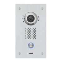
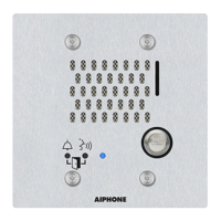
Installation of Audio Only Door Station
When installing the unit on a rough surface, please use sealant to seal the unit edges to prevent water entering the unit. If the unit edges are left unsealed on a rough
surface, IP65 ingress protection rating is not guaranteed.
2
Open the terminal cover and connect the
Cat-5e/6 cable and the low-voltage lines to
the unit.
①
Slide the terminal cover down.
②
Open the terminal cover.
③
Route the wires through inlet.
④
Insert the low-voltage lines and Cat-5e/6 cable, and replace the terminal cover.
Be sure to close the terminal cover when done.
If left open, condensation or water may enter, preventing heat
dissipation and causing damage.
Attach the door station.
Cat-5e/6 cable
Low-voltage lines
Special screws (included) ×4
Inlet
2-gang box
(Depth: 52.5mm(2-1/16") or more)
Unit
Special screwdriver
(included)
Tighten
Loosen
Recommended
Mounting height
(center of gang box)
1,350 mm (4' 5'')
(max.1,900 (6' 2-2/3"))
How to Connect
Connection Precautions
■ Cat-5e/6 cable
• For connection between devices, use a straight-through cable.
• If necessary, when bending the cable, please observe the manufacturer’s recommendations. Failure to do so could cause a communication failure.
• Do not strip away the cable insulation any more than is necessary.
• Perform termination in accordance with TIA/EIA-568A or 568B.
• Before connecting the cable, be sure to verify conduction using a LAN checker or similar tool.
• A RJ45 covered connector cannot be connected to the LAN ports of the master stations or the door stations. Use cables without covers on the connectors.
• Be careful not to pull on the cable or subject it to excessive stress.
■ Precautions regarding low-voltage line
• Use PE (polyethylene)-insulated PVC jacketed cable. Parallel or jacketed conductors, mid-capacitance, non-shielded cable is recommended.
• Never use twisted-pair cable or coaxial cable.
• 2Pr quad V twisted pair cables cannot be used.
■ Connection and disconnection of low-voltage lines
• Insert the line into the quick connection terminal.
• If the line does not go in easily, push the low-voltage line into the terminal while pressing down the detachment button.
• When removing a low-voltage line, pull on the line while pressing down the detachment button.
Detachment
button
Recommended
diameter of wire
ø0.8
8mm (5/16")
* The shape varies depending on a model.
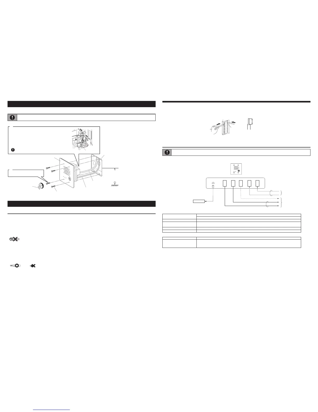
Wiring Connection
• Insulate and secure unused low-voltage lines.
IX-SS-2G
LAN/PoE
※
※
IEEE802.3af
N
O
C
O
M
N
C
S
S
E
Audio Only Door Station
Relay output
※2
Contact input
※1
Cat-5e/6straight
PoE switch
100m (330')
PE0.8(20AWG)-2C
PE0.8(20AWG)-2C
※1 Contact Input Specifications
Input method Programmable dry contact (N/O or N/C)
Level detection method
Detection time 100 msec or more
Contact resistance Make: 700 Ω or less
Break: 3 kΩ or more
Terminal short-circuit current 20 mA or less
Voltage between terminals 5.5 VDC or less (between open terminals)
※2 Relay Output Specifications
Output method Form C dry contact (N/O or N/C)
Contact rating 24 VAC, 1 A (resistive load)
24 VDC, 1 A (resistive load)
Minimum overload (AC/DC): 100 mV, 0.1 mA
 Loading...