EasyManua.ls Logo

Air-Con ACZEM4C4R24 - User Manual

Air-Con ACZEM4C4R24
103 pages
Print Icon
To Next Page IconTo Next Page
Loading...
GREE ELECTRIC APPLIANCES,INC.OF ZHUHAI
Service Manual
Model: ACZEM4C4R18/ACZCI4C4R18
ACZEM4H4R18/ACZCI4H4R18
ACZEM4C4R24/ACZCI4C4R24
ACZEM4H4R24/ACZCI4H4R24
(Refrigerant:R410A)
Question and Answer IconNeed help?

Do you have a question about the Air-Con ACZEM4C4R24 and is the answer not in the manual?

Summary

1. Summary

2. Specifications

2.1 Specification Sheet

Lists detailed technical specifications for the indoor and outdoor units.

3. Outline Dimension Diagram

3.1 Indoor Unit

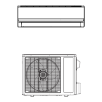
Shows dimensional diagrams and measurements for the indoor unit.

3.2 Outdoor Unit

Shows dimensional diagrams and measurements for the outdoor unit.

4. Refrigerant System Diagram

5. Electrical Part

5.1 Wiring Diagram

Provides wiring diagrams for the indoor and outdoor units.

5.2 PCB Printed Diagram

● Indoor Unit

Displays the printed circuit board layout for the indoor unit.

6. Function and Control

6.1 Remote Controller Introduction

Explains the buttons and icons on the remote controller.

6.2 Brief Description of Modes and Functions

Explains various operating modes, functions, and control features.

(1) Auto mode

(2) Cooling mode

(3) Dry Mode

(4) Fan mode

(5) Heating mode

(6) Compressor control function

(7) 4-way valve control function

3.Other control functions

(1) Timer function

Explains general and clock timer functions for scheduling.

(2) Emergency operation switch

(3) Sleep function

(4) Turbo function

(5) X-FAN function

(6) Indoor fan speed control

(7) Up & down swing

(8) Display of nixie tube on indoor unit

(9) Memory function

(10) Compulsory defrosting function

(11) Refrigerant recycling function

(12) Outdoor fan motor control function

4 Special functions

(1) HEALTH function

Explains the operation and activation of the HEALTH function.

(2) I FEELfunction

Details the I FEEL function for temperature sensing via remote.

5 Main system protection

(1) Indoor fan motor does not operate

Describes the protection triggered by indoor fan motor failure.

(2) Freeze protection

Explains the freeze protection mechanism and error codes.

(3) Overload protection

Details overload protection conditions and error codes.

(4) Compressor high discharge temperature protection

Describes protection for high compressor discharge temperature.

(5) Drop off voltage protection

Explains protection against voltage drop-off.

(6) Communication malfunction

Describes protection for communication failures between units.

(7) IPM module protection

Details IPM module protection and error codes.

(8) Module overheating protection

Explains module overheating protection and error codes.

(9) Compressor overload protection

(10) Overcurrent protection

(11) Temperature sensor malfunction detection

7. Notes for Installation and Maintenance

Safety Precautions: Important!

Provides essential safety warnings and guidelines for installation and maintenance.

Warnings

Highlights potential hazards and necessary precautions.

Electrical Safety Precautions:

Lists precautions related to electrical work and connections.

Refrigerant Safety Precautions:

Details safety measures when handling refrigerants.

Installation Safety Precautions:

Outlines safety measures during the installation process.

Main Tools for Installation and Maintenance

8. Installation

8.1 Installation Dimension Diagram

Shows diagrams illustrating required clearances for installation.

Installation procedures

Provides a flowchart of the installation steps.

8.2 Installation Parts-checking

8.3 Selection of Installation Location

1. Basic Requirement:

Lists unsuitable installation locations and general advice.

2. Indoor Unit:

Details optimal locations and considerations for indoor unit installation.

3. Outdoor Unit:

Outlines criteria for selecting a suitable outdoor unit location.

8.4 Electric Connection Requirement

1. Safety Precaution

Lists essential safety regulations for electrical installation.

2. Grounding Requirement:

Explains the importance and method of proper grounding.

8.5 Installation of Indoor Unit

1. Choosing Installation Iocation

Recommends and confirms the indoor unit installation location.

2. Install Wall-mounting Frame

Details the process of installing the indoor unit's wall-mounting frame.

3. Install Wall-mounting Frame

4. Outlet Pipe

5. Connect the Pipe of Indoor Unit

6. Install Drain Hose

7. Connect Wire of Indoor Unit

8. Bind up Pipe

9. Hang the Indoor Unit

8.6 Installation of Outdoor Unit

1. Fix the Support of Outdoor Unit

Explains how to select a location and fix the outdoor unit support.

2. Install Drain Joint(Only for cooling and heating unit)

Details the installation of the drain joint for cooling/heating units.

3. Fix Outdoor Unit

Describes how to place and fix the outdoor unit onto its support.

4. Connect Indoor and Outdoor Pipes

Explains the process of connecting indoor and outdoor unit pipes.

5. Connect Outdoor Electric Wire

Details how to connect the outdoor unit's electrical wiring.

6. Neaten the Pipes

Provides guidance on neatly routing and bending pipes.

8.7 Vacuum Pumping and Leak Detection

1. Use Vacuum Pump

Explains the procedure for vacuum pumping the system.

2. Leakage Detection

Describes methods for detecting refrigerant leaks.

8.8 Check after Installation and Test Operation

1. Check after Installation

Lists items to check after installation is completed.

2. Test Operation

Details the steps for performing a test operation.

9. Maintenance

9.1 Malfunction Analysis

Provides a flowchart for analyzing common malfunctions.

Poor COOL(HEAT) operation

The fan does not run when it is set to supply air.

In the cooling and heating mode, the compressor runs, but the outdoor fan does not run.

In the cooling and heating mode, the outdoor fan runs, but the compressor does not run.

The compressor is too hot and leads to the action of the protector.

The swing fan does not run.

In cool, heat mode, the outdoor unit and compressor will not run.

Water leakage

Abnormal sound and shake

9.2 Flashing LED of Indoor;Outdoor Unit and Primary Judgement

9.3 How to Check Simply the Main Part

1.Malfunction of Temperature Sensor F1,F2

2. Malfunction of Blocked Protection of IDU Fan Motor H6

3. Malfunction of Protection of Jumper Cap C5

4. Communication malfunction E6

5. Malfunction of Zero-crossing Inspection Circuit Malfunction of the IDU Fan Motor U8

6. Capacitor charging malfunction (outdoor unit malfunction)

7. IPM protection, desynchronizing malfunction, phase current of compressor is overcurrent (outdoor unit malfunction)

8. Diagnosis for high temperature, overload protection

9. Diagnosis for failure start up malfunction (outdoor unit malfunction)

10. Diagnosis for compressor synchronism (outdoor unit malfunction)

11. Diagnosis for overload and discharge malfunction (outdoor unit malfunction)

12. Communication malfunction

Diagnosis process for outdoor communication circuit

10. Exploded Views and Parts List

10.1 Indoor Unit

Shows an exploded view and parts list for the indoor unit.

10.2 Outdoor Unit

11. Removal Procedure

11.1 Removal Procedure of Indoor Unit

Details the steps for removing the indoor unit components.

3. Remove panel

4. Remove electric box cover

5. Remove front case sub-assy

6. Remove vertical louver

7. Remove electric box assy

8. Remove evaporator assy

9. Remove stepping motor

10. Remove motor and cross flow blade

3. Remove horizontal louver

4. Remove electric box cover

5. Remove front case sub-assy

6. Remove vertical louver

7. Remove electric box assy

8. Remove evaporator assy

9. Remove stepping motor

10. Remove motor and motor support.

10. Remove the soundproof sponge

11. Remove 4-way valve assy

12. Remove inhalation tube and discharge pipe and gas-liquid separator

13. Remove gas valve and liquid valve

14. Remove compressor

15. Remove condenser

1. Remove big handle

2. Remove top panel

3. Remove grille

4. Remove panel

5. Remove rear grill and right side plate

6. Remove left side palte

7. Remove axial flow blade

8. Remove motor and motor support.

9. Remove electric box assy

10. Remove the soundproof sponge

11. Remove 4-way valve assy

12. Remove inhalation tube and discharge pipe and gas-liquid separator

13. Remove gas valve and liquid valve

14. Remove compressor

15. Remove condenser

Appendix:

Appendix 1: Reference Sheet of Celsius and Fahrenheit

Provides a conversion table for Celsius and Fahrenheit temperatures.

Appendix 2: Configuration of Connection Pipe

Details connection pipe lengths, refrigerant oil, and charging amounts.

Appendix 3: Pipe Expanding Method

Appendix 4: List of Resistance for Temperature Sensor

Air-Con ACZEM4C4R24 Specifications

General IconGeneral
Power Consumption (Cooling)2200W
RefrigerantR410A
Cooling Capacity24000 BTU
Power Supply220-240V, 50Hz
Operating Temperature (Cooling)18°C to 43°C

Related product manuals