Do you have a question about the AIR GAP Fluidmaster 6000 Series and is the answer not in the manual?
Component for fine-tuning the water level within the cistern.
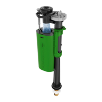
The protective cover for the valve's internal mechanism.
Prevents water from siphoning back into the mains supply.
The main body housing the float and the locking mechanism for height adjustment.
Essential sealing component to ensure a watertight connection.
The threaded connector that attaches the valve to the cistern's water supply.
Component used to secure the valve assembly to the cistern.
Regulates water flow and filters debris from the water supply.
Component for fine-tuning the water level within the cistern.
The protective cover for the valve's internal mechanism.
Prevents water from siphoning back into the mains supply.
The main body housing the float mechanism.
Essential sealing component to ensure a watertight connection.
The threaded connector that attaches the valve to the cistern's water supply.
Component used to secure the valve assembly to the cistern.
Regulates water flow and filters debris from the water supply.
Possible cause: Debris. Solution: Remove and clean diaphragm.
Possible cause: Low flow. Solution: Inspect valves and pipework.
Possible cause: Loose cap. Solution: Ensure cap is fully tightened.
Possible cause: Jammed components. Solution: Ensure free vertical movement.
Possible cause: Unlocked sleeve. Solution: Ensure sleeve is locked down.
Possible cause: Blocked filter. Solution: Remove and clean controller/filter.
Isolate the water supply using the isolation valve or mains stopcock.
Mark water level, drain cistern, and disconnect the valve supply pipework.
Remove the old valve and ensure the fixing hole area is clean.
Fit flow controller/filter for tank-fed or mains/pumped systems.
Ensure the sealing washer is pushed fully onto the threaded shank.
Insert valve through cistern hole with washer inside and nut outside.
Tighten nut by hand, then 1/4 to 1/2 turn with a spanner for a good seal.
Restore water supply and check for leaks and correct flush operation.
Adjust water level using the float adjustment screw and re-flush.
Turn off water, lift float chamber/sleeve to unlock for height adjustments.
Push float chamber/sleeve down to relock after adjusting height.
Details the 5-year limited warranty for Fluidmaster products.
Advisories against bleach/chlorine cleaners and overtightening.
Provides email and website for further information in the UK.
| Brand | AIR GAP |
|---|---|
| Model | Fluidmaster 6000 Series |
| Category | Control Unit |
| Language | English |